
Rapid-densification pressure-coupling dynamic sintering furnace and sintering method

A densification and sintering furnace technology, applied in furnaces, muffle furnaces, cooking furnaces, etc., can solve the problems of difficult sliding rearrangement of particles, lack of real-time monitoring function of axial displacement, and difficulty in discharging pores, so as to prolong service life. Effect

Active Publication Date: 2015-11-18
TSINGHUA UNIV
View PDF8 Cites 15 Cited by
  • Summary
  • Abstract
  • Description
  • Claims
  • Application Information

AI Technical Summary

Problems solved by technology

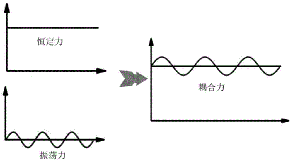
However, the current pressure provided by the hot pressing sintering equipment is constant pressure. Studies have shown that under constant pressure, it is difficult for particles to slide and rearrange, and it is difficult to discharge pores. Especially, nanopowders are prone to spontaneous agglomeration due to their high surface energy. However, constant pressure cannot eliminate its agglomeration, so under the condition of constant pressure sintering, some closed pores often remain at the grain boundary of the material, which restricts the improvement of the mechanical properties of the material.
[0004] In addition, the current sintering equipment often lacks the real-time monitoring function of axial displacement, and the process of powder shrinkage and material densification cannot be grasped in time during the sintering process, thus restricting the formulation of a scientific and reasonable sintering system

Method used


Image

  • Rapid-densification pressure-coupling dynamic sintering furnace and sintering method
  • Rapid-densification pressure-coupling dynamic sintering furnace and sintering method
  • Rapid-densification pressure-coupling dynamic sintering furnace and sintering method

Examples


Embodiment Construction

[0025] The present invention will be described in detail below in conjunction with the accompanying drawings and embodiments.

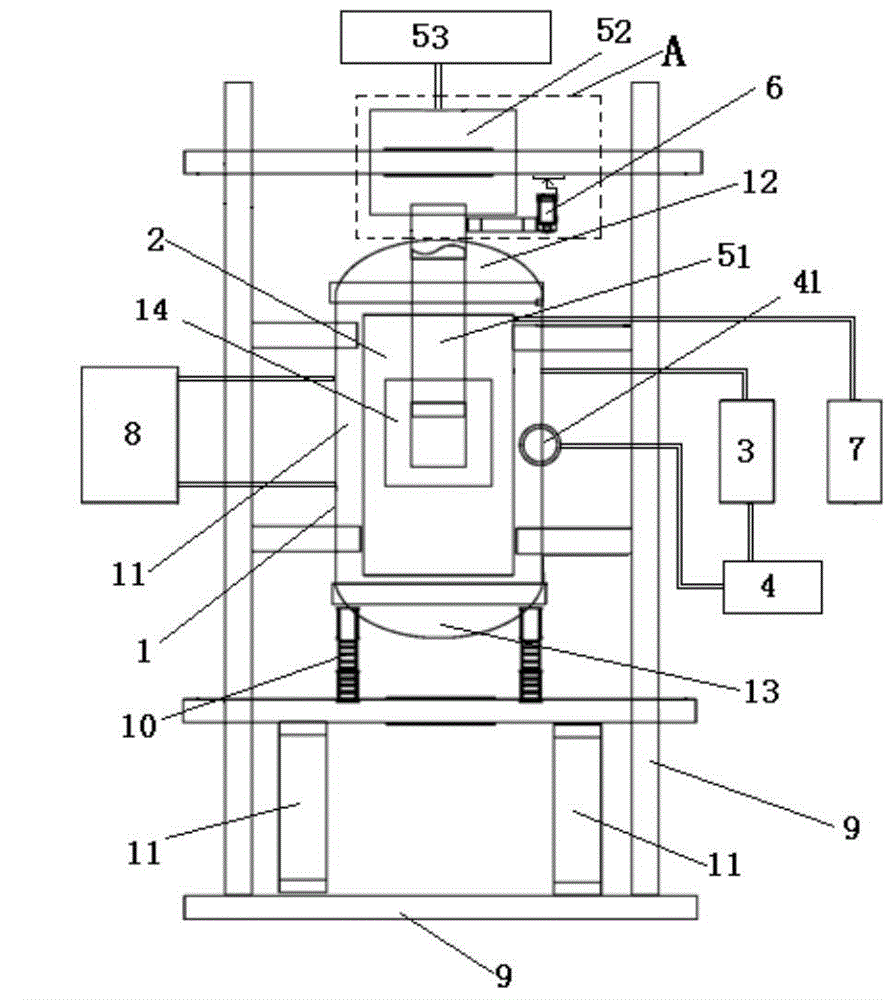
[0026] Such as figure 1 As shown, the present invention provides a rapid densification pressure-coupled dynamic sintering furnace, which includes a furnace body 1 , a heating system 2 , a cooling system 3 , an infrared temperature measurement system 4 and a pressure coupling system 5 . The heating system 2 is located in the furnace body 1, the furnace body 1 is connected to the cooling system 3, the heating system 2 and the cooling system 3 are both connected to the infrared temperature measurement system 4, and the pressure coupling system 5 is connected to the furnace body 1.

[0027] The furnace body 1 includes a furnace shell 11, an upper furnace cover 12 and a lower furnace cover 13. The furnace shell 11 is a sandwich double-walled water-cooled structure. The inner wall of the furnace shell 11, the upper furnace cover 12 and the lower furnace cov...


PUM


Abstract

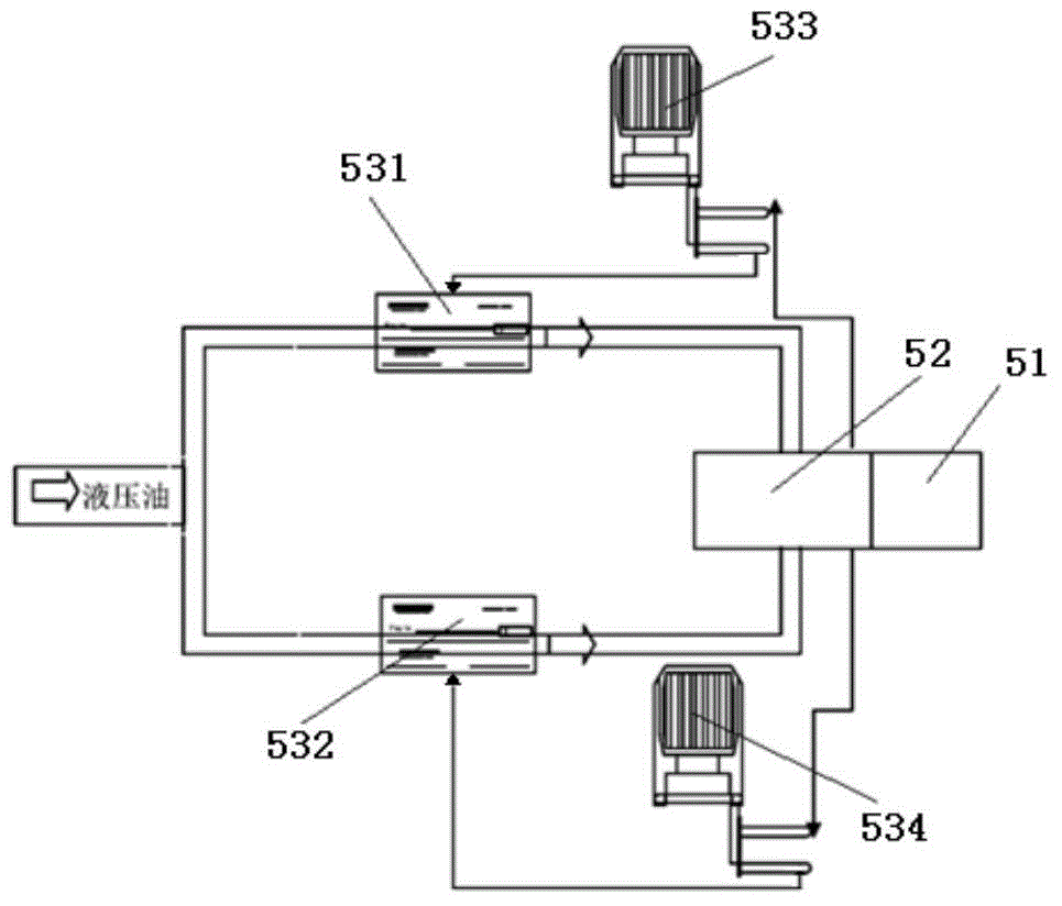
The invention relates to a rapid-densification pressure-coupling dynamic sintering furnace and a sintering method. The rapid-densification pressure-coupling dynamic sintering furnace comprises a furnace body, a heating system, a cooling system, an infrared temperature measurement system and a pressure coupling system, wherein the heating system is positioned in the furnace body, and the furnace body is connected with the cooling system; the heating system and the cooling system are connected with the infrared temperature measurement system, and the pressure coupling system is connected with the furnace body; the heating system is arranged in the furnace body, and the infrared temperature measurement system is connected with the heating system and the cooling system and transmits temperature signals to the heating system and the cooling system; the pressure coupling system comprises a pressure head, a hydraulic cylinder and a pressure control module; the pressure control module comprises a first servo valve, a second servo valve, a constant pressure controller and an oscillation pressure controller, and the pressure coupling system generates the dynamic coupling pressure of frequency and amplitude needed by a material to be sintered. The rapid-densification pressure-coupling dynamic sintering furnace and the sintering method can prepare the material with high density, low defect and high strength and can be widely applied to the sintering process of material preparation.

Description

technical field [0001] The invention relates to a sintering furnace and a sintering method, in particular to a rapid densification pressure coupled dynamic sintering furnace and a sintering method. Background technique [0002] The sintering process in the preparation of advanced materials is a critical step to achieve particle densification and endow materials with mechanical strength. In particular, ceramics and some metal materials have high melting points, and it is often difficult to achieve sintering densification, so higher requirements are put forward for sintering equipment and technology. [0003] The commonly used sintering methods include atmospheric pressure sintering and hot pressing sintering. Atmospheric pressure sintering is to promote the densification of materials by heating under atmospheric pressure, and the densification of general materials is not high. Hot pressing sintering is to apply unidirectional or bidirectional pressure to the powder while he...

Claims


Application Information

Patent Timeline
IPC IPC(8): F27B5/04F27B5/06F27B5/14F27B5/18
Inventor 谢志鹏李双
Owner TSINGHUA UNIV
Learn More