Finned tube and heat exchanger

A finned tube and fin technology, which is applied to tubular elements, heat exchange equipment, lighting and heating equipment, etc., can solve the problems of affecting the heat transfer efficiency of the finned tube and reducing the heat exchange efficiency, so as to achieve a large heating area and reduce The effect of fouling and improving heat transfer efficiency

Inactive Publication Date: 2015-11-11
SOUTHEAST UNIV
View PDF9 Cites 8 Cited by
  • Summary
  • Abstract
  • Description
  • Claims
  • Application Information

AI Technical Summary

Problems solved by technology

However, the longitudinal straight finned tube sacrifices a large part of the extended surface area, which reduces the heat transfer efficiency
[0006] In short, most of the existing finned tube designs are at the expense of sacrificing the heat transfer area and reducing the heat transfer efficiency, which seriously affects the advantages of high heat transfer efficiency of the finned tube.

Method used


Image

  • Finned tube and heat exchanger
  • Finned tube and heat exchanger
  • Finned tube and heat exchanger

Examples


Embodiment 1

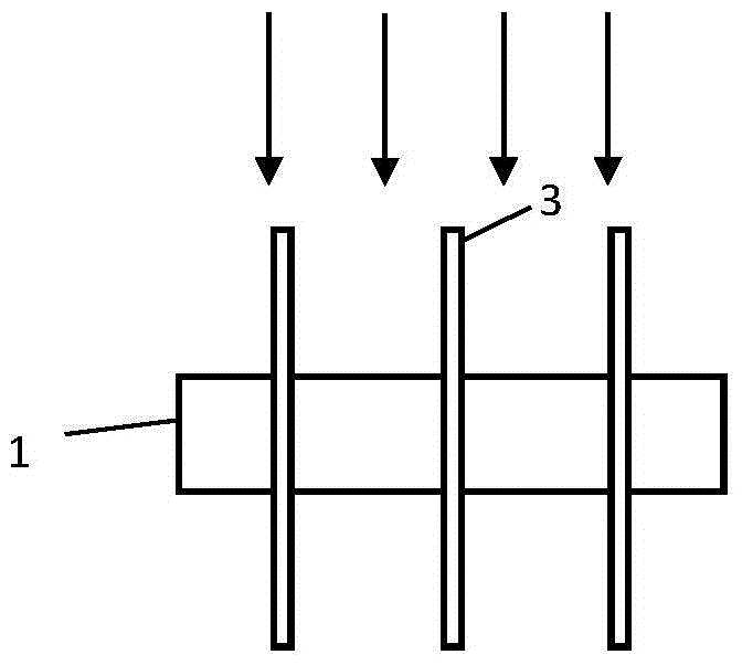
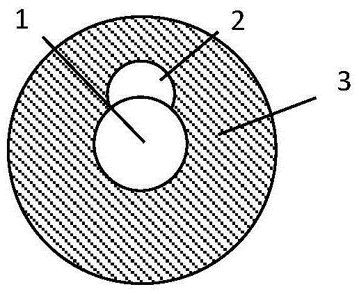
[0033] figure 1 , figure 2 shown. The finned tube of the present invention comprises a base tube 1 and fins 3, wherein the base tube 1 is a base tube, and the fins 3 are circular fins arranged at intervals. Disturbance holes of any shape are opened on the flow-facing surface of the circular fins, and in this embodiment, the shape of the spoiler holes is a semicircular hole 2 . Weld the circular fins with inner openings on the base tube 1, or process the openings on the fins 3 of the existing circular fin tubes.

[0034] Fluent commercial software is used to analyze the traditional circular finned tube of a certain structural size ( Figure 5 , Image 6 ) and the flue gas flow outside the fin tube with spoiler holes of the present invention is numerically simulated:

[0035] The flue gas velocity outside the finned tube is 6m / s, and flows along the positive direction of the x-axis. For the existing traditional circular finned tube, the simulated velocity profile along t...

Embodiment 2

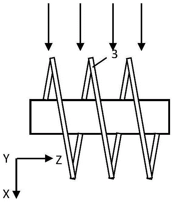
[0041] Such as image 3 and Figure 4 As shown, the fin tube of the present invention includes a base tube 1 and fins 3, wherein the base tube 1 is a base tube, and the fin 3 is a spiral fin. Arbitrary-shaped spoiler holes are opened on the flow-facing surface of the spiral fins, and in this embodiment, the shape of the spoiler holes is a diamond-shaped hole 4 .


PUM


Abstract

The invention discloses a finned tube and a heat exchanger. The finned tube comprises a base tube body and fins arranged on the outer surface of the base tube body. The finned tube is characterized in that a flow disturbing hole enabling flue gas to be disturbed on an incident flow face is formed in the incident flow face of each fin; the flow disturbing holes extend from the inner ends of the fins to the outer ends of the fins, and the outward extending height is 1 / 2 to 2 / 3 of the height of the fins; the fins are parallel fins or spiral fins arranged at intervals. On the premise of guaranteeing the surface expansion rate of the finned tube, the flow characteristic of flue gas outside a pipeline of the heat exchanger can be improved, the flow speed of flue gas in a trailing vortex area of the pipeline is reduced, and therefore ash deposition of the finned tube is relieved.

Description

technical field [0001] The invention is applied in the field of boiler heat exchangers, and in particular relates to a finned tube which can effectively improve the ash deposition characteristics of the heat exchange tube and a heat exchanger with the finned tube. Background technique [0002] The finned tube is an enhanced heat exchange element arranged at the tail of the system flue in order to recover the exhaust heat of power plant boilers, industrial boilers, industrial kilns, ship power plants, etc., and effectively improve the utilization rate of fuel. The finned tube increases the extended surface area of ​​the heat exchange tube by welding the fins on the surface of the light tube, thereby achieving the purpose of enhancing heat transfer. Due to the streamlined fin surface of circular and spiral finned tubes, the wear characteristics of fins are better than those of rectangular fins. Therefore, the commonly used finned tubes in industry include circular finned tubes...

Claims


Application Information

Patent Timeline
Patent Type & Authority Applications(China)
IPC IPC(8): F28F1/12
Inventor 赵伶玲钟磊周强泰
Owner SOUTHEAST UNIV
Why Eureka
Try Eureka