Device for recovering hot air of dry type slag removal machine and reducing disorganized air leakage of bottom of hearth and application thereof

A slag remover and unorganized technology, applied in the field of electric power equipment, can solve the problems of increased desuperheater and reheater desuperheating water volume, reduced secondary air volume, high air leakage rate at the bottom of the furnace, and reduced NOx emission concentration, The effect of reducing the amount of desuperheating water and obvious comprehensive benefits

Active Publication Date: 2015-11-04
GUODIAN NANJING ELECTRIC POWER TEST RES CO LTD
View PDF5 Cites 1 Cited by
  • Summary
  • Abstract
  • Description
  • Claims
  • Application Information

AI Technical Summary

Problems solved by technology

[0004] At present, the dry slag remover generally has the problem of high air leakage rate, and it greatly deviates from the design value of 1% air leakage rate. The air leakage rate of some units exceeds 10%, or even higher. The secondary air volume of the air preheater is further reduced, making the thermal efficiency of the boiler farther away from the optimum value, which affects the economical operation of the unit; the air leakage rate at the bottom of the furnace is higher, which makes the boiler generate nitrogen oxides under high and medium load conditions The increase in the amount of nitrogen oxides will affect the emission control of nitrogen oxides and greatly increase the operating cost; at the same time, because most of the units are mixed with economical coal, the qua...

Method used


Image

  • Device for recovering hot air of dry type slag removal machine and reducing disorganized air leakage of bottom of hearth and application thereof
  • Device for recovering hot air of dry type slag removal machine and reducing disorganized air leakage of bottom of hearth and application thereof

Examples


Embodiment Construction

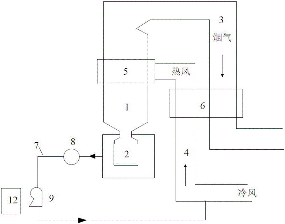
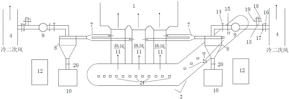
[0019] Equipment for recovering hot air from dry-type slag remover to reduce fugitive air leakage at the bottom of the furnace, see figure 1 and figure 2 , including boiler furnace 1, dry slag remover 2, flue 3, secondary air duct 4, burner 5, air preheater 6, suction pipe 7, cyclone separator 8, suction fan 9, slag Lock box 10, control device 12, ventilation bypass 13, first damper 14, first isolation door 15, second adjustment damper 16, second isolation door 17, third adjustment damper 18, third isolation door 19, plug Panel door 20; dry slag remover 2 is installed at the bottom of boiler furnace 1 and connected through slag pipe 11, flue 3 is installed at the top of boiler furnace 1, and secondary air duct 4 passes through air preheater 6 and burner 5 It is connected with the boiler furnace 1; the burner 5 is respectively connected with the flue 3 and the secondary air duct 4; the slag pipe 11 is connected with the secondary air duct 4 through the suction pipe 7, and the...


PUM


Abstract

The invention provides a device for recovering hot air of a dry type slag removal machine and reducing disorganized air leakage of the bottom of a hearth. The device comprises a suction pipeline, a cyclone separator, a suction fan, a control device, a ventilation bypass, a first control damper, a first isolation valve, a second control damper, a second isolation valve, a third control damper and a third isolation valve. The cyclone separator, the first control damper, the first isolation valve, the suction fan, the ventilation bypass, the second isolation valve and the second control damper are sequentially arranged on the suction pipeline from the inlet to the outlet. The third isolation valve and the third control damper are sequentially arranged on the ventilation bypass from the inlet to the outlet. A slag gate box is arranged at the bottom of the cyclone separator. By means of the device, the disorganized air leakage of the bottom of a furnace is changed to organized air supply, and the thermal efficiency of the furnace is improved to close to the optimum value; the flame center height of the hearth is controlled, temperature reduction water quantity of a superheater and a reheater is reduced, cocking which may happen to the platen superheater is reduced, NOx emission concentration is lowered, and remarkable comprehensive benefits to the unit are achieved.

Description

technical field [0001] The invention belongs to the field of electric equipment, and particularly relates to a device for recovering hot air from a dry slag remover to reduce fugitive air leakage at the bottom of a furnace, and also relates to a device for recovering hot air from a dry slag remover to reduce fugitive air leakage at the bottom of a furnace. Background technique [0002] Dry-type slag removal machine has been valued by the power industry for its energy-saving, water-saving, environmental protection and good comprehensive benefits. At present, hundreds of units have been put into operation with dry-type slag removal machine. Working process of dry slag removal machine: high temperature slag falls on the conveyor belt of slag discharge machine through the furnace bottom slag discharge door, and uses the negative pressure of the furnace to cool the slag by sucking in ambient air. The cold air absorbs the physical sensible heat of the hot slag and the slag is combu...

Claims


Application Information

Patent Timeline
IPC IPC(8): F23J1/06
Inventor 蔡培宁新宇沈玉兴王双童王庆河
Owner GUODIAN NANJING ELECTRIC POWER TEST RES CO LTD
Why Eureka
Try Eureka