
Heat pump unit structure

A technology of heat pump units and heat exchange tubes, applied in heat pumps, heating and cooling combinations, refrigerators, etc., can solve the problems of high evaporator outlet temperature, low heat exchange efficiency, and high condensation outlet temperature, and achieve safe high and low pressure and Effects of exhaust temperature, heat exchange area increase, and refrigerant flow reduction

Inactive Publication Date: 2015-10-28
GUANGDONG PHNIX ECO ENERGY SOLUTION
View PDF7 Cites 0 Cited by
  • Summary
  • Abstract
  • Description
  • Claims
  • Application Information

AI Technical Summary

Problems solved by technology

[0003] 1. The finned heat exchanger is used as a condenser. Due to the high ambient temperature, the condensation of the unit is poor, resulting in high condensation outlet temperature, which makes the high pressure of the unit higher, which exceeds the normal operating range of the unit;
[0004] 2. The tubular heat exchanger is used as an evaporator. Since the water temperature is relatively high under the T3 working condition, the evaporation of the unit is very good, but due to poor condensation, the outlet temperature of the evaporator will be high, and the return air temperature of the system will be too high, thus The exhaust temperature of the system is too high, and the exhaust temperature exceeds the normal operating range of the unit;
[0005] 3. Due to the characteristics of high pressure and high exhaust temperature of the heat pump unit operating under the T3 working condition, the unit can generally only use R22 / R407C refrigerant, and R22 is a simple refrigerant, which has a great impact on the environment and has low heat transfer efficiency. High, R407C is a non-azeotropic mixed refrigerant, the heat transfer efficiency is not high, and there is a temperature slip, which makes the temperature detection of the unit inaccurate, and there is a deviation of about 7 °C
[0006] Therefore, how to further improve the structure of the unit, solve the problems of high pressure and high exhaust temperature when the unit is refrigerated under the T3 working condition, and improve the heat exchange efficiency of the unit are technical problems that need to be solved by those skilled in the art

Method used


Image

  • Heat pump unit structure

Examples


Embodiment Construction

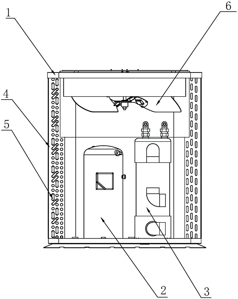
[0019] refer to figure 1 , the present invention is a heat pump unit structure, including a heat pump unit box 1, a compressor 2 and a tubular heat exchanger 3 located in the heat pump unit box 1, a fan blade 6 is arranged on the top of the heat pump unit box 1, and the heat pump unit box The inner wall of 1 is also provided with a finned heat exchanger 4 composed of several fins and copper tubes 5 interspersed in each fin. The length of the heat exchange tube is compressed towards the bottom.

[0020] The structure of this heat pump unit extends the fins that form the finned heat exchanger to the inside of the heat pump unit box 1, so that the heat exchange area of ​​the heat exchanger increases, thereby enhancing the condensation effect during cooling, and compressing the tube heat exchanger 3 at the same time The length of the medium heat exchange tube reduces the refrigerant flow and weakens the evaporation of the unit during cooling. When the unit is heating, the tube he...


PUM


Abstract

The invention discloses a heat pump unit structure. According to the heat pump unit structure, fins forming a finned heat exchanger extend towards the interior of a heat pump unit box, so that the heat exchange area of the heat exchanger is increased, and the condensation effect in the refrigerating process is enhanced; meanwhile, the length of a tubular heat exchanger is reduced, so that the flow path of coolants is shortened, and the evaporation capacity of the unit in the refrigerating process is weakened; when the unit conducts heating, the tubular heat exchanger serves as a condenser, and the finned heat exchanger serves as an evaporator; when the environment temperature is about 15 DEG C to 43 DEG C and is low relative to the temperature in the refrigerating process, the finned heat exchanger is improved in order to meet the condensation requirement, and the condensation capacity and evaporation capacity of the unit in the refrigerating process can still be guaranteed. Since the evaporator and the condenser which have unequal heat exchange capacities are arranged, the heat pump unit structure have safe high pressure and low pressure and the safe exhaust temperature when operating in a high-temperature environment on the T3 work condition and can operate stably and reliably. The heat pump unit structure is applied to the field of heat pump unit structures.

Description

technical field [0001] The invention relates to the field of swimming pool heat pumps, in particular to a heat pump unit structure. Background technique [0002] Traditional heat pumps match the capabilities of the evaporator and condenser to achieve better energy efficiency. However, under the T3 working condition, when the unit realizes cooling, there are the following problems: [0003] 1. The finned heat exchanger is used as a condenser. Due to the high ambient temperature, the condensation of the unit is poor, resulting in high condensation outlet temperature, which makes the high pressure of the unit higher, which exceeds the normal operating range of the unit; [0004] 2. The tubular heat exchanger is used as an evaporator. Since the water temperature is relatively high under the T3 working condition, the evaporation of the unit is very good, but due to poor condensation, the outlet temperature of the evaporator will be high, and the return air temperature of the syst...

Claims


Application Information

Patent Timeline
Patent Type & Authority Applications(China)
IPC IPC(8): F25B29/00
CPCF25B30/02
Inventor 雷朋飞高翔刘远辉王星何雄
Owner GUANGDONG PHNIX ECO ENERGY SOLUTION
Learn More