A fully open sliding door structure for a drying room

An open-type, drying room technology, applied in the direction of drying room/container, dryer, etc., can solve the problems of low work efficiency, hidden safety hazards, time-consuming and labor-intensive problems, and achieve the effect of improving efficiency, closing tightly, and improving safety performance

Active Publication Date: 2017-03-08
SHANGHAI UNIV OF ENG SCI
View PDF12 Cites 0 Cited by
  • Summary
  • Abstract
  • Description
  • Claims
  • Application Information

AI Technical Summary

Problems solved by technology

[0006] 1. Driving the turbine and worm with the remote rod requires manual operation by the operator, and in actual factory operation, it takes a lot of effort to lift the gate to the designated position, and during the movement, two to three gaps are required to complete the lifting process , time-consuming and labor-intensive, increasing the physical burden of the operator, and the work efficiency is low
[0007] 2. The hoisting frame of the gate is manually operated, and the accuracy, safety and reliability of the hoisting are low
[0008] 3. With the increase in the number of times the worm gear is used, it will inevitably cause a certain loss, and it will also cause a certain safety hazard to the operator who lifts the gate. Because the gate itself is heavy, this structure has certain dangers. Affect the working efficiency of the drying room and the service life of the door lifting device

Method used


Image

  • A fully open sliding door structure for a drying room
  • A fully open sliding door structure for a drying room
  • A fully open sliding door structure for a drying room

Examples


Embodiment Construction

[0040] The structure of the present invention will be further described in detail below in conjunction with the accompanying drawings.

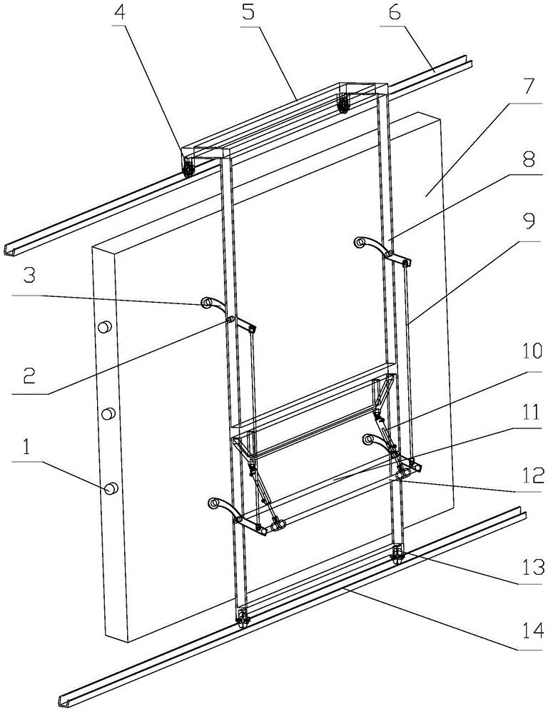
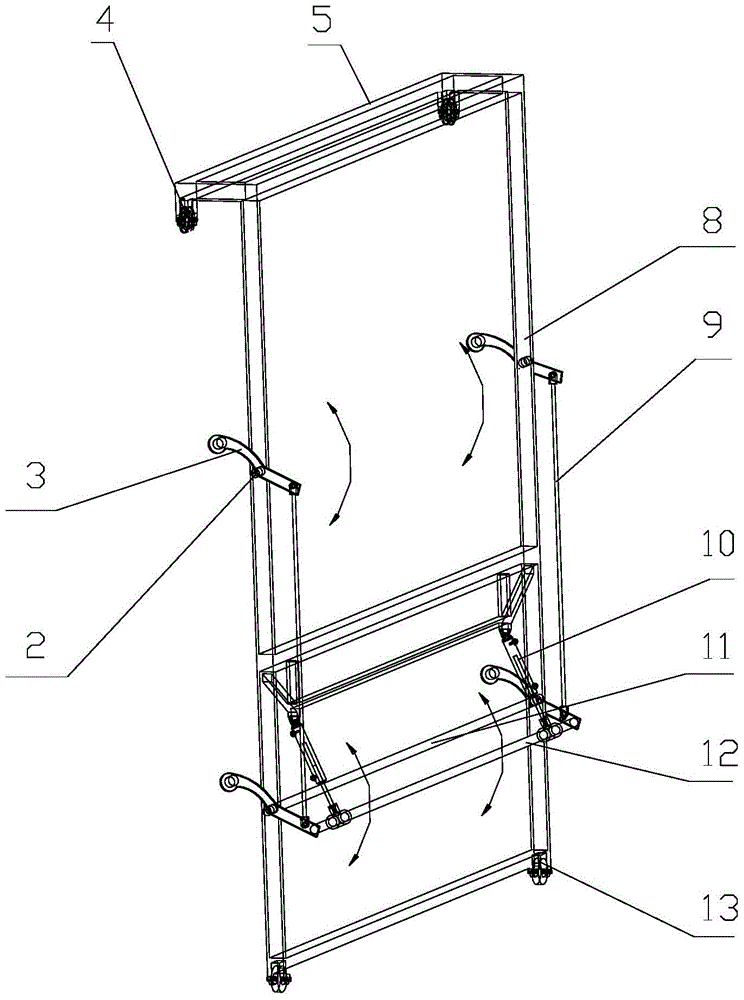
[0041] A fully open sliding door structure for a drying room, said structure comprising a door frame of the drying room, a moving frame located outside the door frame that can move left and right, and an insulating door panel 7 moved by the moving frame;

[0042] The upper and lower parts of the left and right poles 8 of the moving frame are respectively equipped with crank arm rockers 3 that can swing up and down. A part of the crank arm rocker 3 is located outside the moving frame, and a part is located inside the moving frame. fixed on the pole 8 by the pin shaft 2;

[0043] The inner ends of the crank rockers 3 on the left and right sides are respectively connected in rotation by two left and right vertically arranged linkage connecting rods 9; The top or bottom of the inner end, or the upper and lower sides are connected at the same tim...


PUM


Abstract

The invention relates to a front door structure of a drying room for drying wood. A fully-open type sliding door structure of the drying room for drying comprises a door frame of the drying room for drying, a movable frame located on the outer side of the door frame, and an insulating door sheet (7). Crank arm rocking bars (3) capable of swinging up and down are arranged on a left vertical bar (8) and a right vertical bar (8) of the movable frame. The inner ends of the crank arm rocking bars (3) are rotationally connected through two perpendicularly-arranged linkage connecting bars (9). The two sides of a horizontally-arranged force-carrying connecting rod (12) are rotationally connected with two DG type hydraulic cylinders (10) of a synchronizing circuit structure respectively. The four outer ends of the crank arm rocking bars (3) are rotationally connected to the inner sheet surface of the insulating door sheet (7). Two bottom pulleys (13) are arranged at the bottom of the movable frame and two top pulleys (4) are arranged at the top of the movable frame. A plurality of cylindrical positioning bosses (1) are arranged on the left side face and the right side face of the insulating door sheet (7). Manual operation intensity is relieved, and the safety of a front door of the drying room for drying in the opening and closing processes is improved; time is shortened, working efficiency is improved, and service life is long.

Description

technical field [0001] The invention relates to the door structure of a wood drying room, in particular to the opening and closing method and structure of the drying room door. Background technique [0002] Drying operation is an indispensable production link in many fields of the national economy, especially the most energy-consuming but indispensable link in processing industries such as wood, medicine, food, chemical products, and agricultural and sideline products. [0003] Wood drying is the basic link of wood processing and utilization, and its energy consumption accounts for about 40% to 70% of the total energy consumption of wood product production. Correct and reasonable drying treatment of wood is not only the key to ensure the quality of wood products, but also an important means to save energy and reduce costs. Wood drying room is the main equipment for wood products processing. The drying room is a rectangular house structure, and the internal long boards stac...

Claims


Application Information

Patent Timeline
Patent Type & Authority Patents(China)
IPC IPC(8): F26B25/12
Inventor 谭志昊严平吴一帆严佳俊范乐羊
Owner SHANGHAI UNIV OF ENG SCI
Why Eureka
Try Eureka