
Joint structure used for flow casting control and weld stopping control of POCT chip product ultrasonic welding

A technology of ultrasonic welding and joint structure, applied in applications, household components, household appliances, etc., can solve the problems of large deviation of detection results, poor control of welding depth, and influence of fluid flow in microchannels, etc., to achieve high accuracy , Solve the effect of poor welding accuracy

Inactive Publication Date: 2015-10-07
DALIAN UNIV OF TECH
View PDF6 Cites 5 Cited by
  • Summary
  • Abstract
  • Description
  • Claims
  • Application Information

AI Technical Summary

Problems solved by technology

[0006] 1) The ability to control the molten polymer is poor during the welding process. Under pressure and high-frequency vibration, the molten polymer is cast and spread, and it is easy to block the microchannel
[0007] 2) The ability to control the welding depth is poor, and the height of the channel after welding is uneven, which affects the flow mode of the fluid in the microchannel, resulting in the accuracy of subsequent medical testing
[0008] 3) The joint structure is sensitive to welding parameters, the consistency of welding between chips is poor, and the deviation of test results is large, which affects the stability of subsequent medical tests and makes quantitative analysis difficult
[0009] 4) The internal stress generated by welding is too large, and it is easy to open welding and crack during transportation and use
[0012] 2) The requirements for welding precision are high, and the joint structure of macroscopic devices is difficult to meet its precision requirements
The size of macroscopic devices is generally more than several millimeters, and the welding precision deviation is relatively large, which does not meet the requirements of POCT chips
[0013] 3) The tape casting control ability of the existing joint structure is poor, and the molten polymer tape spreading during the welding process will block the microchannel, affecting the detection results and accuracy
[0014] 4) The control ability of the existing joint structure to stop welding is poor, and it is difficult to achieve a uniform height of the microchannel during the welding process, which will have a greater impact on the subsequent detection results

Method used


Image

  • Joint structure used for flow casting control and weld stopping control of POCT chip product ultrasonic welding
  • Joint structure used for flow casting control and weld stopping control of POCT chip product ultrasonic welding
  • Joint structure used for flow casting control and weld stopping control of POCT chip product ultrasonic welding

Examples


Embodiment Construction

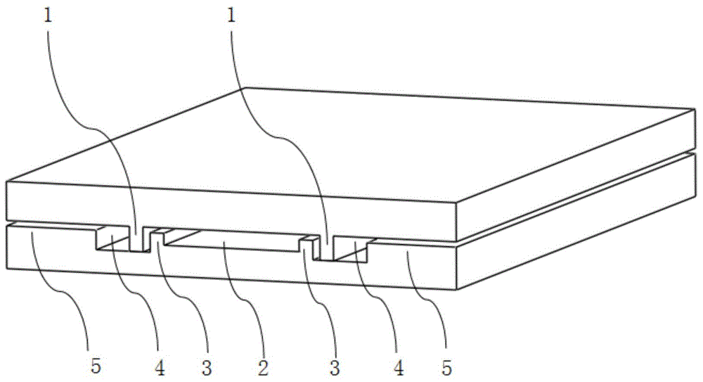
[0035] The specific embodiment of the present invention will be described with reference to the accompanying drawings.

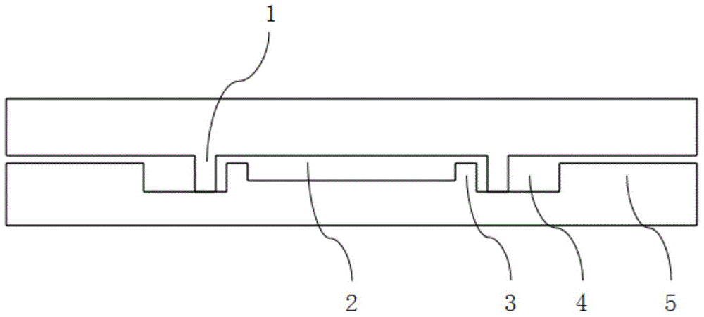
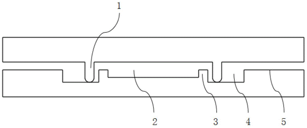
[0036] figure 1 It is a three-dimensional structural view of the present invention, including: energy director 1 , microchannel 2 , flow blocking platform 3 , welding pool 4 , and soldering stop platform 5 .

[0037] The shape of the end of the energy director 1 can be rectangle, triangle and semicircle. figure 2 is the structural view of the rectangular energy director, image 3 is the structural view of the semicircular energy director, Figure 4 It is the structural view of the triangular energy director.

[0038] The alignment between the cover sheet and the substrate is realized through the cooperation of the energy director 1 and the welding pool 4 .

[0039] In the ultrasonic welding process, most of the welding energy will gather near the energy director. When the energy exceeds a certain value, the energy director will melt first. Due to the ex...


PUM

PropertyMeasurementUnit
widthaaaaaaaaaa
widthaaaaaaaaaa

Abstract

The invention provides a joint structure used for flow casting control and weld stopping control of POCT chip product ultrasonic welding. The joint structure is characterized in that a micro channel, weld ponds, weld stopping platforms and flow blocking platforms are formed in a substrate; energy-oriented ridges are formed in a cover plate; the cover plate is installed on the substrate, and the alignment and location between the cover plate and the substrate are achieved through the cooperation between the energy-oriented ridges and the weld ponds; in the ultrasonic welding process, molten polymers are stored in the weld ponds, the polymers are prevented from overflowing, and the melting and flow casting control of the polymers is achieved; a large amount of welding energy is absorbed through the weld stopping platforms, the fusion welding operation of the energy-oriented ridges is stopped, and the weld stopping control is achieved. By means of the joint structure, the problems that in the ultrasonic welding process of a POCT chip, the micro channel is prone to being blocked, and the control accuracy of the channel height is poor are solved, and the joint structure has the advantages of being simple in structure, convenient to align and high in welding strength.

Description

technical field [0001] The invention relates to a joint structure used for flow control and welding stop control of ultrasonic welding of POCT chip products, and belongs to the technical field of medical polymer POCT chip product manufacturing. Background technique [0002] With the rapid development of science and technology, medical inspection work is moving towards a simple and instant stage. POCT (Point Care of Testing) refers to the testing performed by hospital professionals or non-professionals outside the traditional testing center, also known as bedside testing. POCT has the characteristics of rapid acquisition of test results, use of whole blood samples, less sample consumption, short sample turnaround time, miniaturization of instruments, and instant result reporting. The application of POCT technology simplifies traditional disease detection methods, replaces detection equipment that requires high maintenance costs, and expands from the initial blood sugar and p...

Claims


Application Information

Patent Timeline
Patent Type & Authority Applications(China)
IPC IPC(8): B29C65/08
CPCB29C66/54B29C65/08B29C65/7829B29C66/112B29C66/1122B29C66/114B29C66/30223B29C66/322B29C66/71B29C66/73921B29C66/8322B29L2031/756B29K2025/08
Inventor 李经民周立杰刘冲梁超刘军山王立鼎
Owner DALIAN UNIV OF TECH
Learn More