
Solar power bank structure

A technology of mobile power supply and solar energy, which is applied in the direction of current collectors, electric vehicles, electrical components, etc., and can solve the problems of rechargeable batteries with complicated specifications, battery power exhaustion, and inability to charge

Inactive Publication Date: 2015-09-30
吴铭远
View PDF0 Cites 1 Cited by
  • Summary
  • Abstract
  • Description
  • Claims
  • Application Information

AI Technical Summary

Problems solved by technology

[0004] However, when the current rechargeable battery is exhausted, it still needs to be recharged frequently to maintain the power. However, the current charging device generally converts the electric energy of the battery into the electric energy of the battery, which cannot be charged outdoors. The situation of being exhausted and unable to charge in time causes great inconvenience to users, and the specifications of rechargeable batteries on the market are complicated, and not a single charger can cooperate. This is also an inconvenience. Therefore, how to further improve the use of chargers The convenience is actually a technical issue with industrial applicability

Method used


Image

  • Solar power bank structure
  • Solar power bank structure
  • Solar power bank structure

Examples


no. 1 example

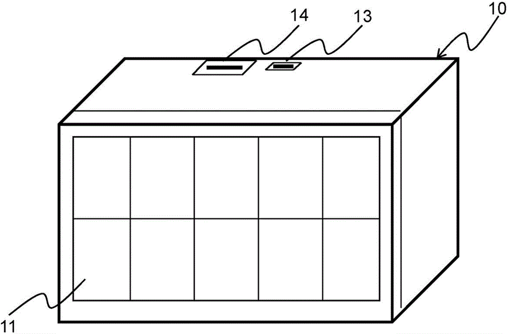
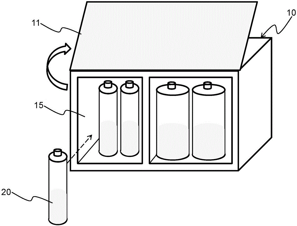
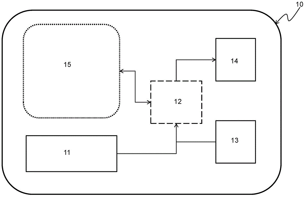
[0037] Rechargeable battery accommodating slots 15 of different specifications are arranged at appropriate positions in the casing 10. The accommodating slots 15 can be horizontally designed to accommodate rechargeable batteries of different appearance specifications (the cylindrical batteries of different sizes are shown in the figure, except The appearance shown in the figure can also be designed as a flat or square-shaped accommodating slot for general-purpose rechargeable batteries). This rechargeable battery can be charged by the solar panel 11 when the power is exhausted, or the receiver 13 can be used to receive external Power charging. When the rechargeable battery is fully charged, it can be placed in the accommodating slot 15 to provide working power to the transmission unit 14 for use by other devices, or taken out of the accommodating slot 15 to be used as a general household battery. Please refer to figure 2 , This is a three-dimensional (2) diagram of the first em...


PUM


Abstract

A solar power bank structure is disclosed. A power bank housing comprises a plurality of charging battery receiving slots in different specifications and at least one external connecting interface. After the external of the housing is provided with a solar reception plate for receiving solar energy, the solar energy is converted into working power and transmitted to the external connecting interface so as to be used by other devices. The work power can charge charging batteries of various types through the charging battery receiving slots without consuming any resources. If no light source is available, the power bank provides electric power to other devices through the charging batteries in the charging battery receiving slots, and can receive external electric power from the external connecting interface during charging. The external electric power after being converted by a working unit is transmitted to the charging battery receiving slots to charge the charging batteries of various types. The charging batteries can be taken out from the housing to serve as common household batteries. The structure is convenient and portable, and the use convenience of the power bank is improved.

Description

Technical field [0001] The present invention relates to a mobile power supply structure; in particular, it relates to a mobile power supply structure using solar energy, which has the characteristics of energy saving and is suitable for charging various rechargeable batteries and supplying power to other devices for use. Background technique [0002] Thanks to the increasing advancement of science and technology, most of the devices in people’s lives have the convenience of being portable, but these portable devices need battery devices to provide the power they need during operation, but in the past, batteries generally consumed power. It needs to be discarded and replaced to continue the operation of the device when it is exhausted. It consumes resources and because the internal components of the battery can cause damage to the environment, it is not environmentally friendly. Therefore, the traditional battery type has developed a rechargeable battery. To meet people's needs. ...

Claims


Application Information

Patent Timeline
IPC IPC(8): H02J7/00H02J17/00
CPCH02J5/005H02J7/025H02J7/35
Inventor 吴铭远
Owner 吴铭远
Learn More