A laser circulation cooling system and its control method

A circulating cooling system and laser technology, applied in the field of lasers, can solve the problems of temperature jump, overall weight increase, large volume of closed water tank, etc., and achieve the effect of ensuring precise control, stable operation and accuracy

Active Publication Date: 2018-03-20
CHINA ELECTRONICS TECH GROUP CORP NO 16 INST
View PDF4 Cites 1 Cited by
  • Summary
  • Abstract
  • Description
  • Claims
  • Application Information

AI Technical Summary

Problems solved by technology

[0003] The existing laser cooling system water cooling units have the following deficiencies: 1. The large number of water pumps causes the overall power consumption to increase, and the volume of the airtight water tank is too large to increase the overall weight
2. Even if the outlet pressure of the water pump adapts to the work of the sensitive device inside the laser, due to the excessive local pressure drop of the sensitive device, the outlet pressure of the fluid after passing through the sensitive device is low, and the resistance of the fluid to the plate heat exchanger cannot be overcome, resulting in The chain reaction causes insufficient circulating flow of the fluid in the whole process; at the same time, since the temperature measurement point is at the outlet of the plate heat exchanger, the boiling heat transfer of the refrigerant in the plate heat Heat is not easy to control. If the process lacks measures to offset the temperature change process, it will easily lead to large temperature fluctuations.

Method used


Image

  • A laser circulation cooling system and its control method
  • A laser circulation cooling system and its control method
  • A laser circulation cooling system and its control method

Examples


Embodiment Construction

[0032] The present invention will be further described below in conjunction with accompanying drawing:

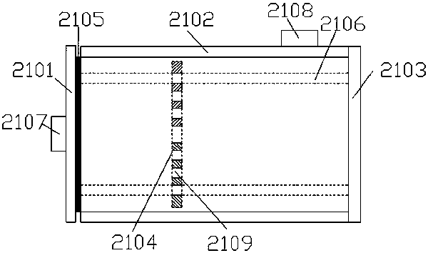
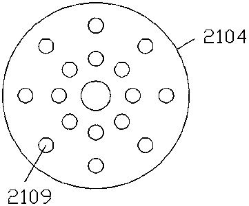
[0033] like figure 1 A laser circulation cooling system shown includes a cooling side system 1, a cooling side system 2 and a main control system.

[0034] The refrigeration side system 1 includes a gas-liquid separator 11 , a compressor 12 , a condenser fan assembly 13 , a filter 14 , a first solenoid valve 15 , an expansion valve 16 , a second solenoid valve 17 and a plate heat exchanger 18 . The outlet of the gas-liquid separator 11 is connected with the inlet of the compressor 12 . The outlet of the compressor 12 is connected with the inlet of the condenser fan assembly 13 and the second electromagnetic valve 17 respectively. The outlet of the condenser fan assembly 13 is connected to the first inlet of the plate heat exchanger 18 through the filter 14 , the first solenoid valve 15 , the expansion valve 16 and in turn. The first outlet of the plate heat exchanger 18 ...


PUM


Abstract

The invention relates to a laser circulation cooling system and a control method thereof. The cooling system includes a cooling side system, a load cooling side system and a main control system. The cooling side system includes gas-liquid separator, compressor, condenser fan assembly, filter, first solenoid valve, expansion valve, second solenoid valve and plate heat exchanger. The load-cooling side system includes a buffer water tank for uniformly mixing fluids with temperature differences, a high-efficiency filter, a first regulating valve, a second regulating valve, a flow sensor, a first proportional valve, an ion adsorber, a closed water tank, a water pump and a second Two proportional valves. A temperature sensor is arranged on the pipeline between the high-efficiency filter and the first regulating valve. A conductivity detection device and a liquid level switch are arranged in the airtight water tank. The invention can not only meet the flow and pressure requirements of sensitive devices inside the laser, but also can precisely control the temperature of the fluid to ensure the stable operation of the refrigeration compressor.

Description

technical field [0001] The invention relates to the technical field of lasers, in particular to a laser circulation cooling system and a control method thereof. Background technique [0002] The sensitive devices in the internal structure of the laser are relatively precise, and the working capacity is low, and the local resistance is high. Therefore, the water quality requirements of the cooling system water-cooling unit are relatively high, generally involving temperature control accuracy, filtration accuracy and outlet pressure. [0003] The existing laser cooling system water cooling unit has the following disadvantages: 1. The large number of water pumps increases the overall power consumption, and the volume of the closed water tank is too large to increase the overall weight. 2. Even if the outlet pressure of the water pump adapts to the work of the sensitive device inside the laser, due to the excessive local pressure drop of the sensitive device, the outlet pressure...

Claims


Application Information

Patent Timeline
Patent Type & Authority Patents(China)
IPC IPC(8): H01S3/04H01S5/024F25B1/00
Inventor 陈诚
Owner CHINA ELECTRONICS TECH GROUP CORP NO 16 INST
Why Eureka
Try Eureka