
Wireless network communication real-time monitoring system and monitoring method

A wireless network communication and real-time monitoring technology, which is applied in the field of communication and computer, can solve the problems of high cost, high communication cost, unsuitable for remote monitoring, etc., and achieve the effect of reducing communication cost, improving accuracy and reliability, and extending distance

Inactive Publication Date: 2015-09-09
STATE GRID SHANDONG LINQU POWER SUPPLY +2
View PDF8 Cites 8 Cited by
  • Summary
  • Abstract
  • Description
  • Claims
  • Application Information

AI Technical Summary

Problems solved by technology

Compared with the traditional analog monitoring system, the digital monitoring system has more powerful functions. However, most of the current video monitoring uses wired network monitoring or local area network monitoring, and wired network monitoring needs to arrange cables or network cables, which is costly and less expensive. It is suitable for remote monitoring, and LAN monitoring is also limited by long-distance distance. Although there are some wireless monitoring methods using GPRS or ZigBee, pure GPRS wireless monitoring can achieve long-distance communication, but due to high communication costs, It is also limited by some occasions, and the pure ZigBee wireless monitoring method, although the cost is effectively reduced, is still limited by a certain distance. Therefore, how to provide a convenient, low-cost, and long-distance remote monitoring , and the transmission of video information is accurate, and it is not easy to break down or distort video transmission, which is a technical problem that people always need to solve

Method used


Image

  • Wireless network communication real-time monitoring system and monitoring method

Examples


Embodiment Construction

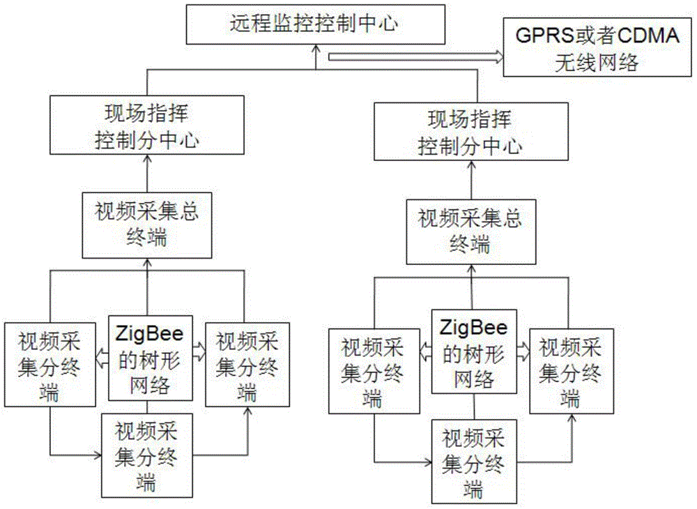
[0023] The present invention provides a wireless network communication real-time monitoring system, which includes a remote monitoring control center, a plurality of on-site command and control sub-centers, a plurality of video acquisition main terminals and a plurality of video acquisition sub-terminals corresponding to each video acquisition main terminal, A ZigBee wireless network communication connection is adopted between any adjacent two of a plurality of said video collection sub-terminals corresponding to the same video collection main terminal, and each said video collection sub-terminal is connected with the corresponding said video collection main terminal. The ZigBee wireless network is used for communication connection, and each on-site command and control sub-center corresponds to one of the video acquisition master terminals.

[0024] A wired network connection is used between the video collection main terminal and its corresponding on-site command and control su...


PUM


Abstract

The invention provides a wireless network communication real-time monitoring system and monitoring method, which adopt a manner of general packet radio service (GPRS) or code division multiple access (CDMA) wireless network combination, so that the communication cost can be lowered effectively, in addition, long-distance remote video monitoring can be realized, video information is processed through a packaging mechanism, a channel coding mechanism and an error recovery mechanism, the correct rate and reliability of video transmission are effectively improved, and monitoring faults are not easy to occur; every video acquisition sub-terminal can adopt a relay transmission manner, information collected by remote video acquisition sub-terminals is transmitted to near video acquisition sub-terminals, and the collected information is sent out by the near video acquisition sub-terminals, so that the distance of remote monitoring is effectively extended; in addition, a global positioning system (GPS) and a global system for mobile communications (GSM) short message module are adopted, thereby ensuring that immediate location at the first moment is performed and monitors are warned once monitoring information becomes abnormal.

Description

technical field [0001] The invention belongs to the field of communication and computer technology, and relates to a remote monitoring and wireless communication technology, in particular to a wireless network communication real-time monitoring system and a monitoring method. Background technique [0002] Video surveillance technology has been widely used in unattended power stations, urban road traffic, oil field reservoirs, banks, factories and mines, construction, distance education and other occasions due to its intuitive, convenient and rich information content. In recent years, the traditional analog monitoring methods have been gradually replaced by digital monitoring methods, and remote digital video monitoring has become a new development direction. Compared with the traditional analog monitoring system, the digital monitoring system has more powerful functions. However, most of the current video monitoring uses wired network monitoring or local area network monitor...

Claims


Application Information

Patent Timeline
Patent Type & Authority Applications(China)
IPC IPC(8): H04N7/18
Inventor 邱梅庞占星刘晓亮陈万强赵晓雪郎需栋马华杰
Owner STATE GRID SHANDONG LINQU POWER SUPPLY
Learn More