
Starting method for brushless direct-current excitation synchronous motor

A synchronous motor and DC excitation technology, which is applied in the direction of AC motor control, generator control, motor generator control, etc., can solve problems such as difficult to achieve control effect, low starting success rate, and low motor load capacity

Active Publication Date: 2015-09-09
ZHUZHOU NAT ENG RES CENT OF CONVERTERS
View PDF6 Cites 8 Cited by
  • Summary
  • Abstract
  • Description
  • Claims
  • Application Information

AI Technical Summary

Problems solved by technology

The starting method mentioned in the papers "Application of High Voltage Frequency Converter to Increased Safety Brushless Excitation Synchronous Motor" and "Research on Variable Frequency Operation Mode of Brushless Synchronous Motor" can reduce the starting current, but the open loop method is difficult to achieve better The control effect of the motor is not strong, and the load capacity of the motor is not strong; at the same time, the motor speed fluctuates greatly during the whole step of excitation, which may easily cause the inverter to over-current or the module to trip due to over-voltage, and the starting success rate is not high
The synchronous motor involved in the patent "Starting Control Method and Device of Aeronautical Three-Stage Electric Excitation Synchronous Motor" is quite different from the ordinary brushless synchronous motor. Said control method is also different from the present invention
Because the brushless DC excitation synchronous motor can only be started asynchronously, the closed-loop vector control or torque control strategy of ordinary brushed synchronous motors cannot be directly used

Method used


Image

  • Starting method for brushless direct-current excitation synchronous motor
  • Starting method for brushless direct-current excitation synchronous motor
  • Starting method for brushless direct-current excitation synchronous motor

Examples


Embodiment Construction

[0057] The present invention will be further described below in conjunction with the accompanying drawings and specific embodiments.

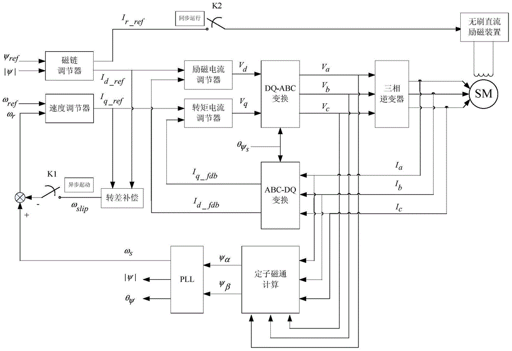
[0058] like figure 2 As shown, the starting method of the brushless DC excitation synchronous motor in this embodiment includes the asynchronous starting closed-loop vector control process, the transitional closed-loop vector control process and the synchronous closed-loop process executed sequentially. The specific process is:

[0059] S1. Asynchronous start closed-loop vector control process: according to the synchronous motor three-phase stator current I a , I b and I c , get the three-phase reference voltage V a , V b , V c , output to the stator winding of the synchronous motor through PWM modulation for excitation;

[0060] S2. Transitional closed-loop vector control process: when the speed of the synchronous motor reaches the preset speed, the excitation of the stator winding is gradually switched to the excitation by the brushles...


PUM


Abstract

The invention discloses a starting method for a brushless direct-current excitation synchronous motor. The method includes the following steps of: S1, asynchronous starting closed-loop vector control process: three-phase reference voltage Va, Vb and Vc can be obtained according to three-phase stator current Ia, Ib and Ic of the synchronous motor, and the three-phase reference voltage Va, Vb and Vc c are subjected to pulse-width modulation and are outputted to stator windings of the synchronous motor so as to perform excitation; S2: transition closed-loop vector control process: when the rotation speed of the synchronous motor achieves preset rotation speed, excitation provided by the stator windings is gradually switched to excitation provided by a brushless direct-current excitation device; and S3: synchronous closed-loop control process: when all excitation is switched to excitation provided by the brushless direct-current excitation device, the synchronous motor enters a synchronous operation process. The starting method for the brushless direct-current excitation synchronous motor of the invention has the advantages of simple control, low starting current, excellent speed adjusting performance and high starting torque.

Description

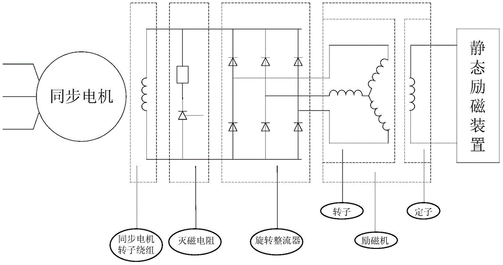
technical field [0001] The invention mainly relates to the technical field of motor control, in particular to a starting method of a brushless DC excitation synchronous motor. Background technique [0002] Because there are no brushes and collector rings, the brushless synchronous motor avoids the generation of sparks, simplifies the operation and maintenance procedures, and reduces the damage of brush dust to the motor insulation. Wide range of applications. At the same time, due to the removal of vulnerable components such as carbon brushes, the overall reliability of the motor is greatly improved, and there are many applications in some occasions that require continuous long-term high-reliability operation. [0003] The structure principle of brushless DC excitation synchronous motor and excitation system is as follows: figure 1 As shown, the main difference between it and the ordinary brushed synchronous motor is the excitation system. The brushless DC excitation syste...

Claims


Application Information

Patent Timeline
IPC IPC(8): H02P21/00H02P25/02
Inventor 彭勃曹洋罗仁俊吴强秦灿华肖伟张志李嘉陈孟君黄欢杨磊唐建宇梁文超陶洪亮
Owner ZHUZHOU NAT ENG RES CENT OF CONVERTERS
Learn More