On-site roadbed dynamic response testing method and system thereof
A technology for roadbed power and field testing, which is applied in measurement devices, instruments, scientific instruments, etc., can solve the problems of difficulty in obtaining data, insufficient systematicness, and large influence of system vibration, and achieves high research efficiency, wide applicability, and reliable structure. Effect
- Summary
- Abstract
- Description
- Claims
- Application Information
AI Technical Summary
Problems solved by technology
Method used
Image
Examples
Embodiment 1
[0043] according to Figure 4 As shown, a test method for on-site testing of roadbed dynamic response during road construction and operation, the steps are:
[0044] ① Select highway structure 1 with flat terrain and straight route as the test road;
[0045] ② Fill the embankment 5, road bed 6 and road surface 7 horizontally in layers from bottom to top;
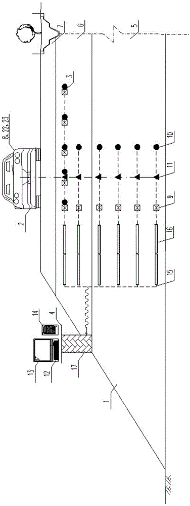
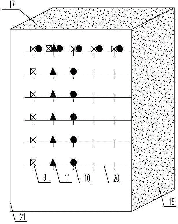
[0046] ③ Arrange the first dynamic pressure sensor 9, the second acceleration sensor 10, and the third temperature and humidity sensor 11 on the central cross-section of the test road section according to the 'Γ' shape. If the roadbed construction has exceeded the first dynamic pressure sensor 9 and the second acceleration sensor 10 , The third temperature and humidity sensor 11 is pre-embedded at the elevation, and the first dynamic pressure sensor 9, the second acceleration sensor 10, and the third temperature and humidity sensor 11 are installed by drilling and slotting layered embedding methods; otherwise, the roadbed i...
Embodiment 2
[0054] Such as Figure 1 ~ Figure 3 shown. A test system for on-site testing of roadbed dynamic response during road construction and operation, consisting of a road structure 1 , a traffic dynamic load system 2 , an information sensing system 3 , and a data acquisition system 4 . It is characterized in that: the first dynamic pressure sensor 9, the second acceleration sensor 10, and the third temperature and humidity sensor 11 in the information sensing system 3 are buried layer by layer in the embankment 5 and the road bed 6 in the road structure 1, and the first The dynamic pressure sensor 9, the second acceleration sensor 10, and the third temperature and humidity sensor 11 are respectively connected to one end interface of the corresponding transmission cable 15, and the other end interface of the transmission cable 15 is connected to the data acquisition system located outside the road structure The signal interface of the dynamic and static strain acquisition and analy...
PUM
 Abstract
Description
Claims
Application Information
 - Generate Ideas
- Intellectual Property
- Life Sciences
- Materials
- Tech Scout
- Unparalleled Data Quality
- Higher Quality Content
- 60% Fewer Hallucinations
Browse by: Latest US Patents, China's latest patents, Technical Efficacy Thesaurus, Application Domain, Technology Topic, Popular Technical Reports.
© 2025 PatSnap. All rights reserved.Legal|Privacy policy|Modern Slavery Act Transparency Statement|Sitemap|About US| Contact US: help@patsnap.com


