Roof high-voltage box installation structure

A technology of installation structure and high-voltage box, which is applied in the direction of electrical components, substation/switch layout details, etc., can solve the problems affecting the electrical performance of high-voltage components, the impact of silicone rubber material hydrophobicity, and the impact on the operation safety of EMUs, so as to save manpower and Water source, reduce electrical discharge performance, and reduce the effect of cleaning times

Inactive Publication Date: 2015-09-02
CRRC CHANGCHUN RAILWAY VEHICLES CO LTD
View PDF10 Cites 3 Cited by
  • Summary
  • Abstract
  • Description
  • Claims
  • Application Information

AI Technical Summary

Problems solved by technology

Therefore, high-voltage components are easily affected by external rain, fog, pollution, airflow, ultraviolet rays and other environments, causing breakdown or discharge, which seriously affects the operation safety of EMUs
Moreover, the outer insulating material of the high-voltage parts of the roof is mostly made of silicone rubber. After the high-voltage parts are contaminated, they must be cleaned and cleaned every time they return to the warehouse. This cleaning will seriously affect the hydrophobicity of the silicone rubber material, which will directly affect the high-voltage Electrical performance of components

Method used


Image

  • Roof high-voltage box installation structure
  • Roof high-voltage box installation structure

Examples


Embodiment Construction

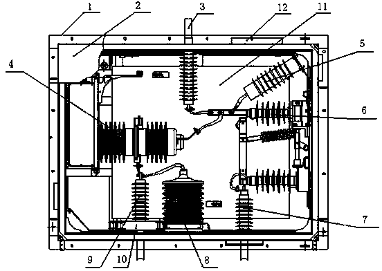
[0013] refer to figure 1 , figure 2 The high-voltage box 1 adopts a glass fiber reinforced plastic top cover 2, and the inner bottom surface of the high-voltage box is laid with GTO-3 laminated boards 11 to increase the electrical clearance between the high-voltage connection point and the ground of the box body. Avoid the impact of impurities in the FRP material on the electrical clearance, so that the FRP top cover becomes an insulating top cover; the vacuum main circuit breaker 4, voltage transformer 8, current transformer 10, isolation switch 6, lightning arrester 5, and three high-voltage The cable head and all components are installed on the side wall of the box body. After installation, ensure that the top cover is flush with the roof and reduce wind resistance at the same time. The high-voltage power supply of the EMU is introduced into the high-voltage box by the first high-voltage cable head 9 and divided into two paths: one path enters the voltage transformer;...


PUM


Abstract

A roof high-voltage box installation structure is disclosed. A high-voltage box adopts a glass fiber reinforced plastics top cover. A laminated board is laid on an inner bottom surface of the high-voltage box. An inner surface of the glass fiber reinforced plastics top cover is sprayed with an anti-pollution flashover coating layer. A vacuum main circuit breaker, a voltage transformer, a current transformer, a disconnecting switch, a lightning arrester and three high-voltage cable heads are integrated in the box. A high voltage power supply of a motor train unit is introduced into the high-voltage box by a first high-voltage cable head and is divided into two branches. One branch enters into the voltage transformer. The other branch passes through the vacuum main circuit breaker and then is divided into two branches. One branch is led out by a second high-voltage cable head and the other branch passes through a high-voltage disconnecting switch and is led out by a third high-voltage cable head. The current transformer sleeves the first high-voltage cable head and collects current signals. The lightning arrester, the disconnecting switch and the second high-voltage cable head are connected in parallel. By using the structure of the invention, an influence of an environment on electrical performance of a high voltage component is avoided. Cleaning frequencies are reduced, and manpower and water sources are saved. In addition, an influence of cleaning on the high voltage component is reduced. Discharging performance of an electric appliance is decreased. An insulating plate is laid on the inner bottom surface of the high-voltage box so that an electric clearance between a high voltage wiring point and ground of a high-voltage box body is increased.

Description

technical field [0001] The invention provides an installation structure of a high-voltage box on a vehicle roof. Background technique [0002] The main function of the high-voltage system of the EMU is to obtain single-phase AC25KV high-voltage power from the catenary, to provide power for the train, to realize the main functions of power supply, electrical protection, and monitoring network voltage and working current. Once the high-voltage system of the EMU has a fault such as discharge, it will cause the EMU to be delayed and passengers will be stranded, and it will seriously cause the power supply of the entire catenary to be cut off, thereby affecting the operation of the entire line of vehicles. Therefore, ensuring the safety and reliability of the EMU high-voltage system directly ensures the operation safety of the EMU. [0003] At present, the high-voltage system components of EMUs are mostly installed directly on the roof, directly connected through high-voltage ca...

Claims


Application Information

Patent Timeline
Patent Type & Authority Applications(China)
IPC IPC(8): H02B1/46H02B1/48
Inventor 张国芹
Owner CRRC CHANGCHUN RAILWAY VEHICLES CO LTD
Why Eureka
Try Eureka