
A method for carrying out dielectric loss and capacitance measurement on a transformer without detaching incoming cables

A technology for transformers and capacitance, applied in the field of transformers, can solve the problems of not correctly reflecting the operation of the transformer, affecting the working efficiency of the transformer bushing, affecting the normal operation of the equipment, etc., to achieve safe operation and normal maintenance of manpower and material resources, and high test work efficiency , Improve the efficiency of test work

Inactive Publication Date: 2015-08-26
STATE GRID CORP OF CHINA +1
View PDF5 Cites 1 Cited by
  • Summary
  • Abstract
  • Description
  • Claims
  • Application Information

AI Technical Summary

Problems solved by technology

In the current wiring mode of the transformer, the high-voltage side is connected to the cable through the copper bar. In the traditional method, if it is necessary to measure the dielectric loss and capacitance of the transformer, it is necessary to remove the leads on the high-voltage side of the transformer. Otherwise, the transformer The connected cables will seriously affect the measurement data and cannot correctly reflect the operation of the transformer
However, there are certain safety hazards in the work of removing the lead wires of the transformer. If the work is resumed carelessly, it may even affect the normal operation of the equipment after the test; Casing oil leakage and joint heating

Method used


Image

  • A method for carrying out dielectric loss and capacitance measurement on a transformer without detaching incoming cables

Examples


Embodiment Construction

[0015] The following describes the embodiments of the present invention in further detail with reference to the accompanying drawings:

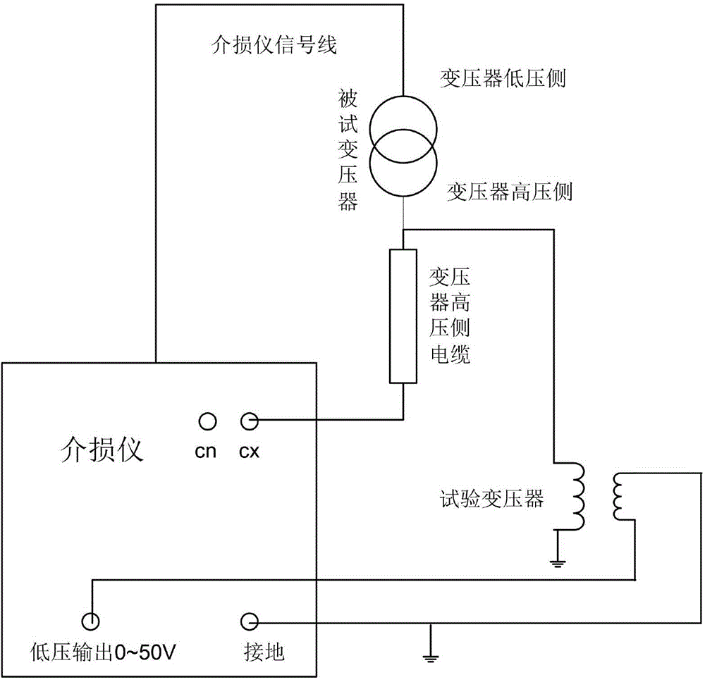
[0016] A method for measuring the dielectric loss and capacitance of a transformer with an incoming cable is in figure 1 Implemented on the measurement system shown. The measurement system mainly uses a dielectric loss tester (dielectric loss tester) and a test transformer. The low-voltage output terminal (0~50V) of the dielectric loss tester is connected to the low-voltage side of the test transformer, and the high-voltage side of the test transformer is connected to the high-voltage side of the tested transformer. The test transformer can usually use a voltage transformer with a rated transformation ratio of 10 / √3 / 0.1 / √3. The voltage output from the low-voltage output of the dielectric loss tester is boosted to the required voltage (usually 10kV) through the test transformer. And connect the high-voltage side of the test transformer to the hi...


PUM


Abstract

The invention relates to a method for carrying out dielectric loss and capacitance measurement on a transformer without detaching incoming cables. The method is characterized in that the method comprises the following steps: a dielectric loss tester, a testing transformer and a tested transformer are connected together; during testing, the cables are connected in series with a dielectric loss tester standard capacitor to serve as a test loop standard capacitor, the transformers form a test loop, the transformer dielectric loss value is obtained by comparing phase relation of standard loop and test loop signals, and the transformer capacitance can be obtained through calculating; and the transformer, of which the dielectric loss and the capacitance are determined, is used as a standard capacitor to form a standard loop, the cables serve as the test loop, and the dielectric loss and the capacitance of the cables can be calculated according to the dielectric loss and the capacitance of the transformer. According to the method, the dielectric loss and the capacitance of the transformer and the cables can be obtained simultaneously without detaching the high-voltage lead wires, so that the purposes of safe operation, normal maintenance and manpower and material resources saving are achieved; and the method has the advantages of being high in test work efficiency, safe and reliable and convenient to use and the like.

Description

Technical field [0001] The invention belongs to the technical field of transformers, in particular to a method for measuring the dielectric loss and capacitance of a transformer with an incoming cable. Background technique [0002] At present, the number of substation equipment in the jurisdiction of each power supply unit is increasing, and the maintenance work is also increasing, which puts forward higher requirements for the test work efficiency of the staff. In the current wiring methods of transformers, the high-voltage side is connected to the copper bar to connect the cable in the form of a large proportion. In the traditional method, if the dielectric loss and capacitance of the transformer need to be measured, the high-voltage side of the transformer needs to be removed. Otherwise, the transformer The connected cable will seriously affect the measurement data and cannot correctly reflect the transformer operation. However, there are certain safety hazards in the work of...

Claims


Application Information

Patent Timeline
Patent Type & Authority Applications(China)
IPC IPC(8): G01R27/26
Inventor 于啸吴仕哲王云龙郭宇维孙振
Owner STATE GRID CORP OF CHINA
Learn More