Chip scale packaging method and structure of light emitting device
A chip-level packaging and light-emitting device technology, applied in the direction of electric solid-state devices, semiconductor devices, electrical components, etc., can solve the problems of increasing production process and cost, unfavorable product miniaturization, unfavorable chip heat dissipation, etc., to ensure color temperature uniformity, Convenience for end users and simplification of manufacturing process
- Summary
- Abstract
- Description
- Claims
- Application Information
AI Technical Summary
Problems solved by technology
Method used
Image

Examples
Embodiment 1
[0045] Such as Figure 10 As shown, a method for chip-scale packaging of light-emitting devices provided in this embodiment is used for packaging of light-emitting devices that do not need to be converted into white light, including steps:
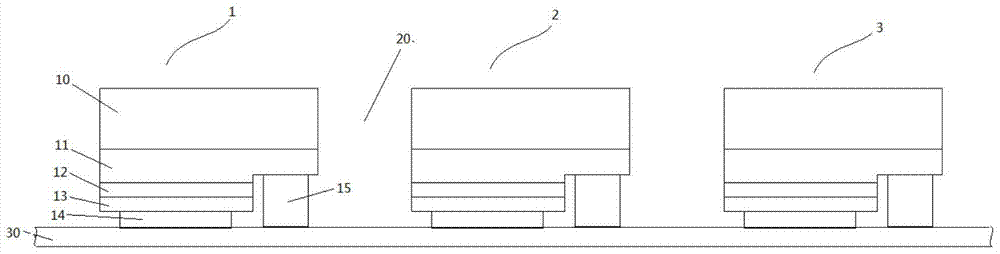
[0046]Step 101: Arranging at least one flip-chip light-emitting device equidistantly on the conversion base film, the main light-emitting surface of the flip-chip light-emitting device is away from the conversion base film, wherein the surface of the conversion base film has a certain viscosity and is durable High temperature, used for adhering the flip-chip light-emitting devices; equidistant in the present invention means that the arrangement distances of multiple flip-chip light-emitting devices in the x-axis and y-axis directions are equal. Here, the conversion base film needs to be resistant to a high temperature of at least 150°C, depending on the nature of the conversion base film. Step 102: Form dams between and / or around the flip...
Embodiment 2
[0062] On the basis of Example 1, combined with Figure 1 to Figure 5 as well as Figure 10 The present invention is described in detail:
[0063] The LED chip of the flip-chip structure comprises a substrate 10, a first semiconductor layer 11, an active region 12 and a second semiconductor layer 13, and the second electrode 14 and the first electrode 15 are connected with the second semiconductor layer 13 and the first semiconductor layer 11 respectively. electrical connection. The conductivity types of the first semiconductor layer 11 and the second semiconductor layer 13 are opposite. The first electrode 15 and the second electrode 14 can comprise multiple layers or a single layer, which include a conductive material layer with high reflectivity, such as a conductive layer made of high reflectivity metals such as Ag, Ru, Al, or a high-transmittance conductive layer. Composite optical film composed of film and highly reflective multilayer dielectric film.
[0064] Multip...
Embodiment 3
[0072] On the basis of embodiment one and two, combine Figure 6 to Figure 8B , provides another example:
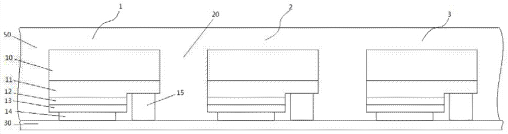
[0073] Such as Figure 6 As shown, on the basis of the second embodiment, dams are formed between and / or around the flip-chip light-emitting devices on the conversion base film.
[0074] Specifically: after a plurality of flip chip LED chips 1, 2, 3 are arranged on the conversion base film 30 at a certain interval 20, a "dam" 80 is formed around the LED chips 1-3. The dam 80 can be formed by sticking a film or other methods, and can be a large dam 80 that is only distributed around all chips or some chips (such as Figure 7A shown) can also be multiple grids (such as Figure 7B Shown) structure, but require the height of the dam 80 to be uniform.
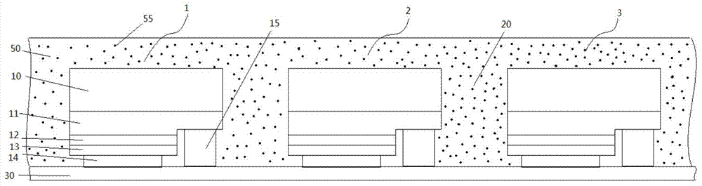
[0075] Apply the prepared encapsulation glue 50 evenly in the dam without air bubbles. The encapsulation glue 50 coated above and around the LED chips 1 - 3 is separated by the dam 80 . The height of the dam 80 exceeds t...
PUM
 Abstract
Description
Claims
Application Information
 - R&D
- Intellectual Property
- Life Sciences
- Materials
- Tech Scout
- Unparalleled Data Quality
- Higher Quality Content
- 60% Fewer Hallucinations
Browse by: Latest US Patents, China's latest patents, Technical Efficacy Thesaurus, Application Domain, Technology Topic, Popular Technical Reports.
© 2025 PatSnap. All rights reserved.Legal|Privacy policy|Modern Slavery Act Transparency Statement|Sitemap|About US| Contact US: help@patsnap.com