Eureka AIR delivers breakthrough ideas for toughest innovation challenges, trusted by R&D personnel around the world.

Waste oil cracking, rectifying and regenerating system

A regeneration system and oil cracking technology, applied in the field of oil purifiers, can solve the problems of difficult production process control, catalyst replacement, difficult equipment adaptation, etc., and achieve the effects of reducing production costs, rational structure, and improving oil yield and quality.

Inactive Publication Date: 2015-08-19
CHONGQING FANGSHENG CLEANING EQUIP CO LTD
View PDF5 Cites 11 Cited by
  • Summary
  • Abstract
  • Description
  • Claims
  • Application Information

AI Technical Summary

Problems solved by technology

At present, there are mainly five kinds of waste oil regeneration processes: acid-base refining method, filter and sieve separation method, centrifugal separation method, gasification separation method, and distillation hydrofining method. Each process and equipment has its own strengths and weaknesses. Although the gasification separation method is recognized as better, the existing gasification separation method equipment is difficult to adapt to medium and small waste oil treatment units. At the same time, the catalyst needs to be replaced frequently, and its production process control is difficult. For this reason, it needs to be improved Waste oil regeneration equipment and technology, exploring a waste oil cracking and rectification regeneration system

Method used


Image

  • Waste oil cracking, rectifying and regenerating system

Examples


Embodiment 1

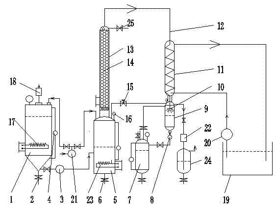
[0018] With reference to the accompanying drawings, a waste oil pyrolysis rectification regeneration system is mainly composed of a dehydration tank 1, a reaction kettle 5, a cooling tower 11, a rectification tower 13, a gas-liquid separation tower 9, an oil storage tank 7, and a waste gas separation tank 24 , a cooling pool 19, and a gas-liquid separation tower vacuum pump 22. The external waste oil is pumped into the dehydration tank 1 or the reactor 5 by the oil inlet pump 21, and the oil in the dehydration tank 1 enters the reactor 5 by the oil pump 3, and the liquid oil is in the reactor. Cracking occurs in 5 to form gaseous oil, and the gaseous oil is rectified in the rectification tower 13. The gaseous oil after rectification enters the cooling tower 11 through the oil and gas pipe 12 to be cooled into liquid oil. The liquid oil and a small amount of miscellaneous gas The liquid separation tower 9 separates, and the liquid oil in the gas-liquid separation tower 9 is tran...

Embodiment 2

[0020] With reference to the accompanying drawings, a waste oil pyrolysis rectification regeneration system is mainly composed of a dehydration tank 1, a reaction kettle 5, a cooling tower 11, a rectification tower 13, a gas-liquid separation tower 9, an oil storage tank 7, and a waste gas separation tank 24 , a cooling pool 19, and a gas-liquid separation tower vacuum pump 22. The external waste oil is pumped into the dehydration tank 1 or the reactor 5 by the oil inlet pump 21, and the oil in the dehydration tank 1 enters the reactor 5 by the oil pump 3, and the liquid oil is in the reactor. Cracking occurs in 5 to form gaseous oil, and the gaseous oil is rectified in the rectification tower 13. The gaseous oil after rectification enters the cooling tower 11 through the oil and gas pipe 12 to be cooled into liquid oil. The liquid oil and a small amount of miscellaneous gas The liquid separation tower 9 separates, and the liquid oil in the gas-liquid separation tower 9 is tran...


PUM


Abstract

The invention discloses a waste oil cracking, rectifying and regenerating system, and relates to an oil purifier. The system is characterized by mainly comprising a dewatering tank, a reaction kettle, a cooling tower, a rectifying tower, a gas-liquid separation tower, an oil storage tank, a waste gas separation tank, a cooling pond and a gas-liquid separation tower vacuum pump, wherein external waste oil is pumped into the dewatering tank or the reaction kettle from an oil inlet pump; the oil of the dewatering tank enters the reaction kettle from an oil well pump; liquid oil is cracked in the reaction kettle to generate gas oil; the gas oil is rectified in the rectifying tower; the rectified gas oil enters the cooling tower to be cooled into the liquid oil through an oil-gas pipe; and the liquid oil and a few of miscellaneous gases are separated in the gas-liquid separation tower. According to the system, a gasification separation process and a distillation process are integrated into a whole; cracking equipment and rectifying equipment for the waste oil are merged into a whole; the system is reasonable in structure; the dewatering, degassing, decolorizing, desulfuration, cracking and rectifying effects of the waste oil are significantly improved; the oil yield and the quality are improved; the production cost for waste oil regeneration is reduced; and the waste oil cracking, rectifying and regenerating system has popularization value.

Description

technical field [0001] The present invention relates to an oil purifier, and more specifically relates to a waste oil pyrolysis rectification regeneration system. Background technique [0002] Waste oil means that after the oil has been used for a period of time, due to the immersion of pollution impurities and the oxidative deterioration of some components, it cannot continue to be used and must be replaced with new oil. The replaced oil is collectively referred to as waste oil. According to national regulations, waste oil is a hazardous waste. Purification and regeneration of waste oil can approach or meet the standards of new oil. It can also regenerate waste oil into fuel oil or base oil, turning waste into treasure and benefiting the country and the people. At present, there are mainly five kinds of waste oil regeneration processes: acid-base refining method, filter and sieve separation method, centrifugal separation method, gasification separation method, and distillat...

Claims


Application Information

Patent Timeline
IPC IPC(8): C10G55/04
Inventor 豆远奎
Owner CHONGQING FANGSHENG CLEANING EQUIP CO LTD
Why Eureka
Eureka Blog
Learn More