Pixel mapping, alignment and imaging for circular and square based microlens arrays for full volume 3D and multidirectional motion

A lens and array technology, applied in the field of three-dimensional images, can solve problems such as difficult control

Active Publication Date: 2017-09-26
LUMENCO
View PDF10 Cites 0 Cited by
  • Summary
  • Abstract
  • Description
  • Claims
  • Application Information

AI Technical Summary

Problems solved by technology

Furthermore, the lens 214 can be molded and reshaped, making printing an identifying image the only obstacle to successfully reproducing the element 200 (and subsequently counterfeiting a piece of currency or product label)
Unfortunately, printing an image 220 has become much more achievable thanks to high resolution lasers and modulators and other printing advancements
Typically, for element 200, the microlenses are printed using the emboss and fill technique, which limits printing to one color due to the fact that the process tends to self-contaminate after one color, and also because the process is based on the relative differences in the emboss and fill process. Hue-to-hue pitch is hard to control

Method used


Image

  • Pixel mapping, alignment and imaging for circular and square based microlens arrays for full volume 3D and multidirectional motion
  • Pixel mapping, alignment and imaging for circular and square based microlens arrays for full volume 3D and multidirectional motion
  • Pixel mapping, alignment and imaging for circular and square based microlens arrays for full volume 3D and multidirectional motion

Examples


Embodiment Construction

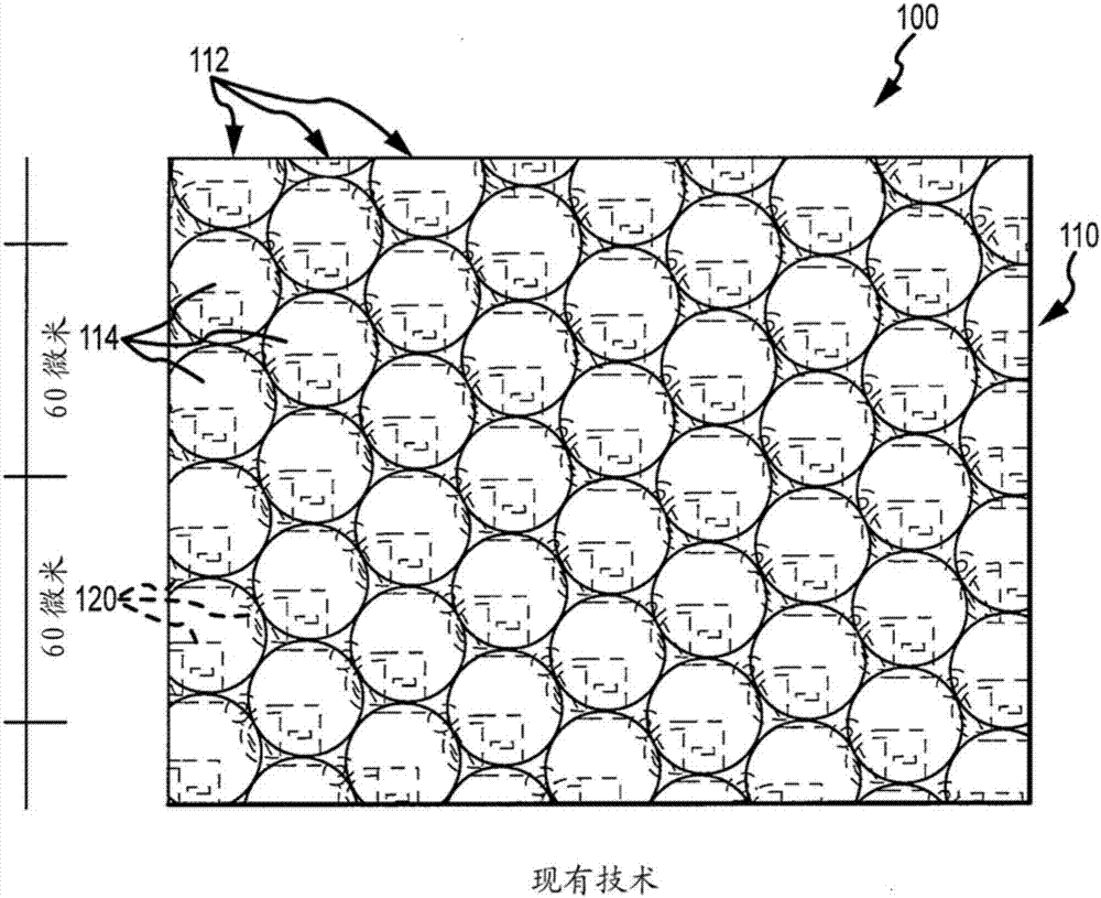
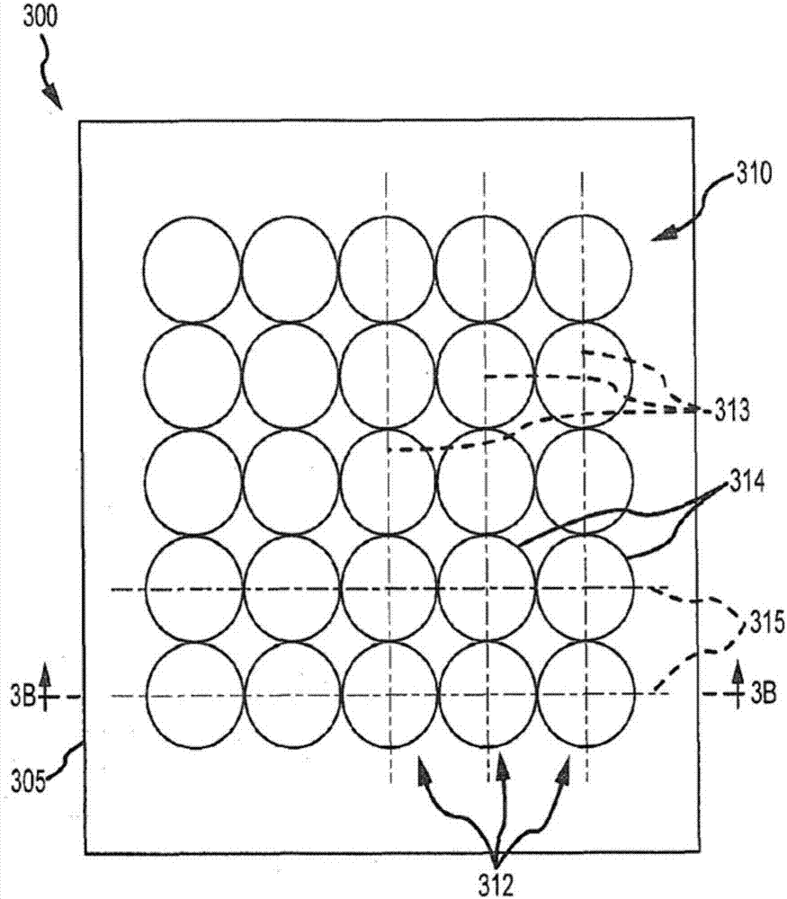
[0039] Briefly, the description is directed to the design of an assembly for combination with a lens array of a printed image provided in an ink layer. A component may be used as, for example but not limited to, a security element or device. lens array with figure 1 with 2 The lens array shown in is partially different in that the lenses are arranged in columns that are not vertically offset, such that the lenses are provided in parallel columns and parallel rows (e.g., adjacent lenses in side-by-side columns have collinear central axis alignment). The lens can be circle or square based, and the underlying image has its pixels mapped and arranged such that the microlens array produces a 3D display image with full volume and, in some cases, multi-directional motion or animation.

[0040] exist Figure 3A with 3B In the embodiment shown in the article 300 (such as a banknote or a label for a product, etc.) has Anti-counterfeiting components or devices. As shown, article 3...


PUM


Abstract

A visual display assembly used as a security device on banknotes, product labels, and other objects. The assembly includes a thin film of transparent material including a first surface including an array of lenses and a second surface opposite the first surface. The assembly also includes a printed image proximate to the second surface. A printed image includes pixels of a frame of one or more images interlaced about two orthogonal axes. The lenses of the array are nested in multiple parallel rows, and adjacent lenses of lenses in columns of the array are aligned in a single row of rows, with lenses in adjacent columns / rows not offset. The lenses may be circular based lenses or square based lenses, and the lenses are provided at 200 lenses per inch (LPI) or higher LPI in both directions.

Description

[0001] Cross References to Related Applications [0002] This application claims the benefit of US Provisional Application No. 61 / 743,485, filed September 5, 2012, which is hereby incorporated by reference in its entirety. technical field [0003] The present invention relates generally to a method for combining printed images with lens arrays to display three-dimensional (3D) images with or without motion, and more particularly to a method suitable for use with square or circular based microlenses to provide full Pixel mapping of volumetric and / or enhanced 3D images with multi-directional motion, providing pixel arrangements and imaging methods. Background technique [0004] There are currently many applications in which it is desired to view a printed image through an array of lenses. For example, anti-counterfeiting efforts often involve the use of an anti-counterfeiting device or element consisting of an array of lenses, and an image printed on the back of the lens arra...

Claims


Application Information

Patent Timeline
Patent Type & Authority Patents(China)
IPC IPC(8): G02B27/22
CPCG02B30/27B41M3/14B42D25/324B42D25/342B41J2/00B42D15/00B44F1/10B42D25/30G06F3/12G09F19/14
Inventor M.A.雷蒙德H.A.P.索托
Owner LUMENCO
Why Eureka
Try Eureka