
Connection test method and device of motherboard CPU (Central Processing Unit) slot based on boundary scan

A connection test and boundary scan technology, applied in the field of motherboard CPU socket testing based on boundary scan, can solve problems such as very high requirements, difficult production, and inability to accurately pin connectivity levels in functional testing, achieving simple production process, The effect of improving test efficiency and improving test coverage

Inactive Publication Date: 2015-07-29
INVENTEC PUDONG TECH CORPOARTION +2
View PDF1 Cites 16 Cited by
  • Summary
  • Abstract
  • Description
  • Claims
  • Application Information

AI Technical Summary

Problems solved by technology

The disadvantage of this test scheme is: the functional test cannot be accurate to the level of pin connectivity, especially for differential signals, the open / short fault of a single line is difficult to show
The disadvantages of this test scheme are: (1) Due to the large number of CPU pins, the number of pins transferred from a single fixture is limited. To test a CPU socket, multiple fixtures are required, and each fixture completes the test of a part of the pins. , and the power needs to be cut off when replacing the fixture
(3) The jig has very high requirements on the manufacturing process and is difficult to manufacture
(4) Limited by the manufacturing process, the pins of the fixture are limited. Even if multiple fixtures are used, the test coverage is still very low, usually only about 11%

Method used


Image

  • Connection test method and device of motherboard CPU (Central Processing Unit) slot based on boundary scan
  • Connection test method and device of motherboard CPU (Central Processing Unit) slot based on boundary scan

Examples


Embodiment Construction

[0022] Embodiments of the present invention will be described below with reference to the drawings. Elements and features described in one drawing or one embodiment of the present invention may be combined with elements and features shown in one or more other drawings or embodiments. It should be noted that representation and description of components and processes that are not related to the present invention and known to those of ordinary skill in the art are omitted from the drawings and descriptions for the purpose of clarity.

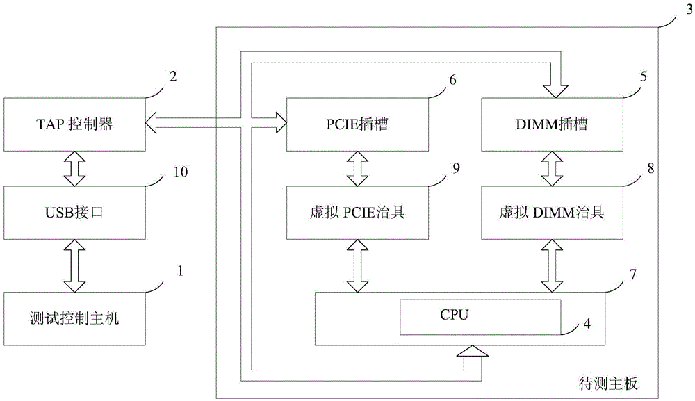
[0023] figure 1 A structural block diagram of a connection testing device for a CPU socket of a motherboard based on boundary scan provided according to an embodiment of the present invention is shown. The connection testing device includes: a test control host 1 , a test access port controller (abbreviated as TAP controller) 2 , and a mainboard 3 to be tested. The motherboard 3 to be tested includes a motherboard CPU 4 , a virtual DIMM fixture 5...


PUM


Abstract

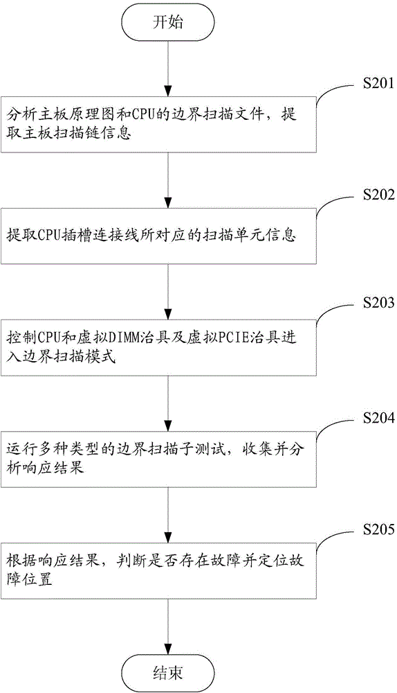
The invention provides a connection test method of a motherboard CPU (Central Processing Unit) slot based on boundary scan, which comprises the following steps of analyzing a to-be-tested motherboard schematic diagram and a boundary scan description language file of a motherboard CPU, a virtual DIMM (dual In-line memory module) jig and a virtual PCIE jig, and extracting scan chain information of the to-be-tested motherboard; extracting scan unit information corresponding to a to-be-tested motherboard CPU slot connecting line; a to-be-tested motherboard CPU, the virtual DIMM jig and the virtual PCIE jig are controlled on a test control motherboard through a TAP controller to enter a boundary scan mode; running multiple types of boundary scan child tests, and collecting and analyzing a responding result; judging whether the to-be-tested motherboard is fault or not and locating the fault position according to the responding result. According to a connection test device and the method, a CPU signal transfer jig is no need to be designed and manufactured, although the virtual DIMM jig and the virtual PCIE jig are needed to be used, the design and the manufacturing process are both simple. Outage for switching hardware in the testing process is not needed. Once the inserting connection of the hardware is finished, all tests can be completed at one time.

Description

technical field [0001] The invention relates to the field of computer motherboard testing, in particular to a boundary scan-based motherboard CPU slot testing method and device. Background technique [0002] The test of the connection of various chip devices on the computer motherboard has always been one of the focuses of the industry in seeking to improve efficiency. Among them, the connection test of the CPU socket has always been a difficult point. Due to the high density of CPU pins, and the contact pins on the socket are arranged obliquely, it is impossible to test by lowering the thimble. At present, the industry usually adopts the following two test schemes for the connection test of the CPU socket. [0003] The first test scenario is: plug in the CPU, start the system, and test the connection by performing a functional test. The disadvantage of this test scheme is that the functional test cannot be accurate to the level of pin connectivity, especially for differe...

Claims


Application Information

Patent Timeline
IPC IPC(8): G06F11/26
Inventor 穆常青
Owner INVENTEC PUDONG TECH CORPOARTION
Learn More