Internal screw thread processing mechanism
A technology of internal thread processing and workbench, which is applied to metal processing machinery parts, metal processing equipment, thread cutting machines, etc., to achieve the effects of easy processing and manufacturing, improved processing efficiency, and simple structure
- Summary
- Abstract
- Description
- Claims
- Application Information
AI Technical Summary
Problems solved by technology
Method used
Image
Examples
Embodiment 1
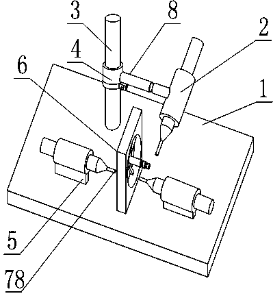
[0020] Such as figure 1 with figure 2 , an internal thread processing mechanism, including a workbench 1, on which a fixing plate 6 for hub fixing is arranged, the upper surface of the workbench 1 is a horizontal plane, and an axial drill 5 and a radial drill 2. Both the axial drill 5 and the radial drill 2 are fixed with a wire cutter, the axis of the wire cutter on the axial drill 5 is parallel to the horizontal plane, and the axis of the wire cutter on the radial drill 2 is inclined relative to the horizontal plane;
[0021] Both the axial drill 5 and the radial drill 2 are fixed on the workbench 1, the axial drill 5 brakes the rotation of the corresponding wire cutter and reciprocates along the axial direction of the wire cutter 78, and the radial drill 5 2 The braking corresponds to the rotation of the wire cutter and the reciprocating movement along the axial direction of the wire cutter 78.
[0022] Specifically, in the present invention, the set fixing plate 6 is us...
Embodiment 2
[0024] Such as figure 1 with figure 2 , this embodiment is further defined on the basis of Embodiment 1: as a structural form that can efficiently complete the tapping process, facilitate the reduction of the volume of the present invention, and avoid the mutual influence of the axial drills 5 on the same side of the fixed plate 6 , there are two axial drills 5 located on different sides of the fixing plate 6, and one radial drill 2.
[0025] As a radial drill 2 fixing structure that is beneficial to ensure that the thread cutter on the radial drill 2 is located in the radial direction of the hub, it also includes a column 3, the column 3 is perpendicular to the upper surface of the workbench 1, and the column 3 is provided with a position at The column 3 is axially adjustable with a shaft sleeve 4 , a connecting rod 8 is fixed on the shaft sleeve 4 , and the radial drill 2 is fixed on the connecting rod 8 .
[0026] In order to facilitate the adjustment of the coaxiality b...
Embodiment 3
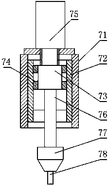
[0028] Such as figure 1 with figure 2 , this embodiment further defines the present invention on the basis of any one of the above embodiments, as a structural form of a radial drill 2 and an axial drill 5 that facilitate the realization of a brake wire cutter, the radial drill 2 and the shaft The drills 5 are all composed of the following parts: installation cylinder 71, bearing bush 72, motor 73, contact slider 74, cylinder 75, wire cutter clip 77, the installation cylinder 71 is tubular, and the bearing bush 72 is fixed on the inner wall surface of the installation cylinder 71 Above, the cylinder 75 is fixed on any one end of the installation cylinder 71, the motor 73 is fixed on the piston rod of the cylinder 75, the thread cutter clip 77 is fixed on the rotor 76 of the motor 73, the piston rod of the cylinder 75, the installation cylinder 71, the rotor 76 three The axes of those are collinear, the contact slider 74 is fixed on the shell of the motor 73, the contact slid...
PUM
 Abstract
Description
Claims
Application Information
 - R&D Engineer
- R&D Manager
- IP Professional
- Industry Leading Data Capabilities
- Powerful AI technology
- Patent DNA Extraction
Browse by: Latest US Patents, China's latest patents, Technical Efficacy Thesaurus, Application Domain, Technology Topic, Popular Technical Reports.
© 2024 PatSnap. All rights reserved.Legal|Privacy policy|Modern Slavery Act Transparency Statement|Sitemap|About US| Contact US: help@patsnap.com


