Feeding method and equipment for warehouse pump in pneumatic conveying system

A technology of pneumatic conveying system and feeding method, which is applied in the direction of conveying bulk materials, conveyors, transportation and packaging, etc., and can solve the problem of arching at the discharge port of the silo, affecting the continuous system output of the pneumatic conveying system, and the feeding of the silo pump. Problems such as poor material flow, to achieve the effect of eliminating arching

Active Publication Date: 2017-04-05
FUJIAN LONGKING
View PDF5 Cites 0 Cited by
  • Summary
  • Abstract
  • Description
  • Claims
  • Application Information

AI Technical Summary

Problems solved by technology

On the other hand, since the diameter of the feed valve connecting the silo pump and the silo is generally small, under the action of the material pressure, arching often occurs above the silo outlet, hindering the falling of the material, even if it is above the silo outlet Installing a gasification plate on the drop pipe often fails to solve the problem; if a long-time feeding method is used to meet the feeding requirements of the warehouse pump, it is very easy to cause material sticking in the exhaust pipe and exhaust valve due to condensation in winter. The blockage problem caused by the junction will affect the continuity and system output of the entire pneumatic conveying system
[0005] In view of the defects of the above-mentioned silo pump feeding device and method, it is urgent to provide a feeding method and feeding equipment that can solve the problem of arching above the silo outlet and poor feeding of the silo pump.

Method used


Image

  • Feeding method and equipment for warehouse pump in pneumatic conveying system
  • Feeding method and equipment for warehouse pump in pneumatic conveying system
  • Feeding method and equipment for warehouse pump in pneumatic conveying system

Examples


Embodiment Construction

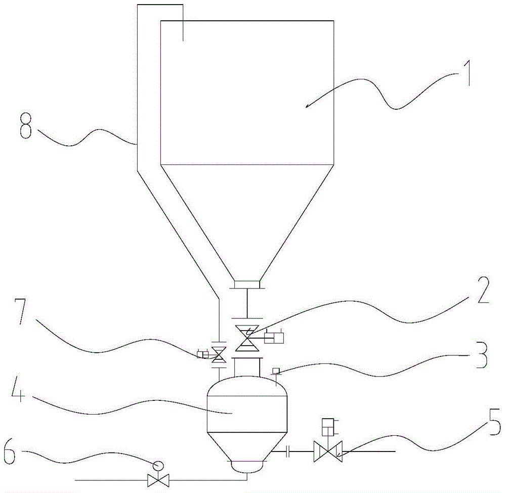
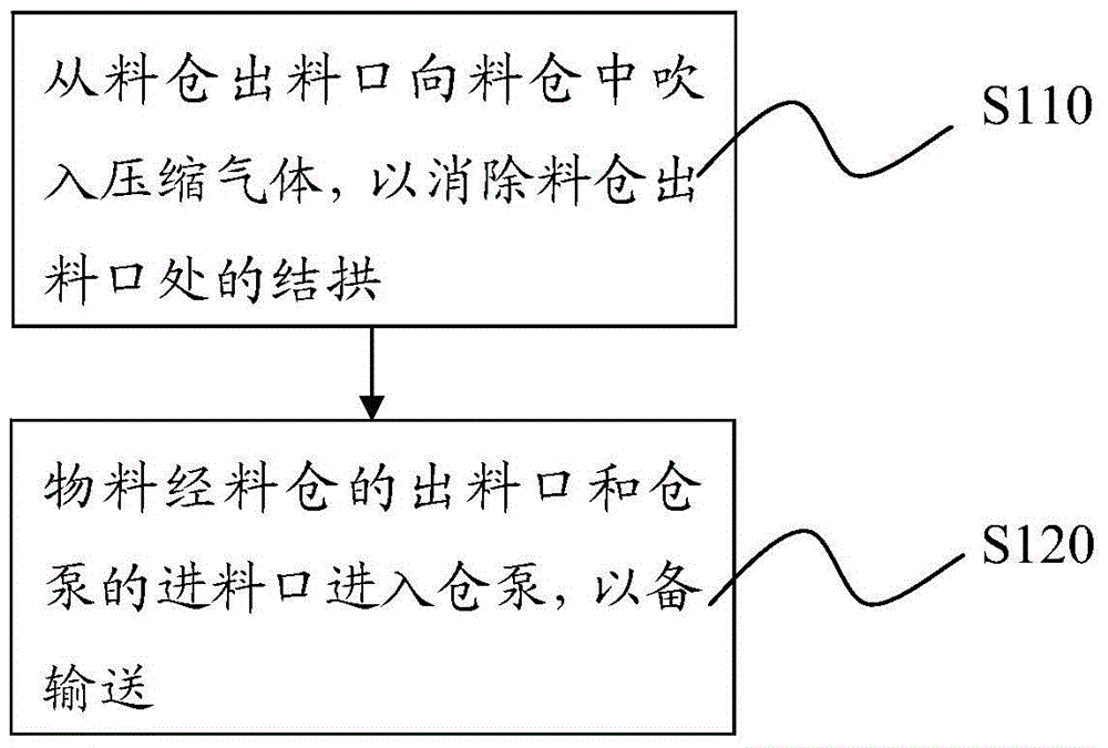
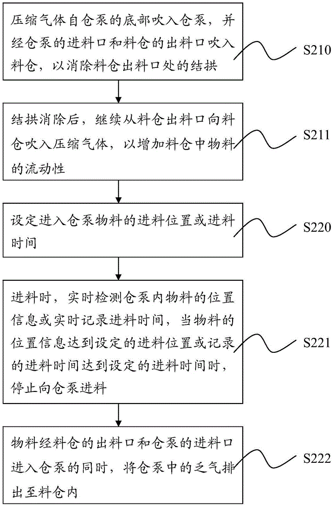
[0032] The core of the present invention is to provide a feeding method and feeding equipment for a warehouse pump in a pneumatic conveying system. The method and equipment use the pressure of compressed air to break through the material at the arch of the silo to eliminate the arch, and at the same time compress the air It can also fluidize the material at the discharge port of the storage bin, improve the fluidity of the material, shorten the feeding time of the warehouse pump, improve the operating efficiency of the warehouse pump, and avoid the leakage of the material due to condensation on the exhaust pipe and exhaust valve. Sticking and clogging.

[0033] In order to enable those skilled in the art to better understand the technical solutions of the present invention, the present invention will be further described in detail below in conjunction with the accompanying drawings and specific embodiments.

[0034] The feeding equipment of the bin pump in the pneumatic convey...


PUM


Abstract

The invention discloses a feeding method and feeding equipment of a cabin pump in a pneumatic conveying system. The feeding method comprises the following steps that 10, compressed gas is blown into a material cabin from a discharging opening of the material cabin, so that the arch forming at the discharging opening of the material cabin is eliminated; 20, materials enter the cabin pump through the discharging opening of the material cabin and a feeding opening of the cabin pump. The invention also provides the feeding equipment for implementing the feeding method. The method and the equipment have the advantages that the compressed gas is blown into the material cabin from the discharging opening of the material cabin, and the arch forming above the discharging opening of the material cabin is eliminated, so that the continuous and stable operation and the system output power of the pneumatic conveying system are ensured.

Description

technical field [0001] The invention relates to the field of engineering transportation, in particular to a feeding method and feeding equipment for a warehouse pump in a pneumatic conveying system. Background technique [0002] Positive pressure dense phase pneumatic conveying technology has a completely closed system, no dust flying, small equipment footprint, flexible layout of conveying pipelines, high conveying efficiency, easy to realize automatic control, and can ensure that the conveyed materials are free from moisture, contamination and mixed with sundries And other advantages, more and more used in the industrial field. [0003] The positive pressure dense phase pneumatic conveying system uses the warehouse pump as the material sending device, which is a relatively reliable dense phase pneumatic conveying device. The warehouse pump of the positive pressure dense phase pneumatic conveying system is installed under the silo, and the silo and the silo pump are connec...

Claims


Application Information

Patent Timeline
Patent Type & Authority Patents(China)
IPC IPC(8): B65G53/66
Inventor 江兴涛潘仁湖田青
Owner FUJIAN LONGKING
Why Eureka
Try Eureka