
Hydraulic brake kinetic energy recovery system for vehicle

A kinetic energy recovery system and hydraulic technology, applied in vehicle parts, auxiliary drive devices, control devices, etc., can solve problems such as affecting the operation and the health of passengers, failing to be widely promoted and applied, and increasing the weight of the whole vehicle.

Inactive Publication Date: 2015-07-15
娄素芳 +2
View PDF6 Cites 2 Cited by
  • Summary
  • Abstract
  • Description
  • Claims
  • Application Information

AI Technical Summary

Problems solved by technology

The disadvantage of this technology is that when the braking time is too long, the flywheel will idle for a long time and rub against the air and bearings, resulting in a large energy loss. It is suitable for short-term braking and re-acceleration when cornering on the track, but not suitable for In modern urban roads, there are driving conditions with a long parking time; in addition, the amount of energy stored by the flywheel depends on the speed and weight of the flywheel. When the speed of the flywheel is too high, the energy loss caused by friction with the air or bearings will increase significantly, while When the weight of the flywheel increases, it will increase the weight of the vehicle at the same time, which will reduce the fuel economy
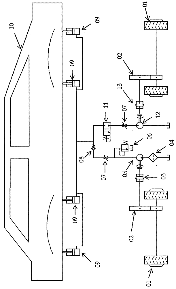
Due to many shortcomings of this technology, it has not been widely applied
[0005] The principle of the electromagnetic braking kinetic energy recovery system is to convert the kinetic energy into electric energy for storage and reuse through the generator set. The disadvantage of this technology is that the power generation depends on the strength of the magnetic field and the number of coils. When the magnetic field is too strong, it will affect the vehicle interior. The operation of other electronic components is related to the health of the passengers. Increasing the number of coils will increase the weight of the vehicle. Therefore, it is currently only used in a few household models, and the power generation is also small. It can only be used as an auxiliary power supply for electrical appliances in the car.

Method used


Image

  • Hydraulic brake kinetic energy recovery system for vehicle
  • Hydraulic brake kinetic energy recovery system for vehicle
  • Hydraulic brake kinetic energy recovery system for vehicle

Examples


Embodiment Construction

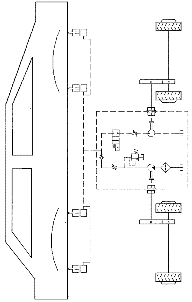
[0013] When the vehicle is running normally, the braking clutch 03 and the driving clutch 13 are both in the disengaged state, and the hydraulic brake kinetic energy recovery system is in the non-working state, such as figure 2 shown.

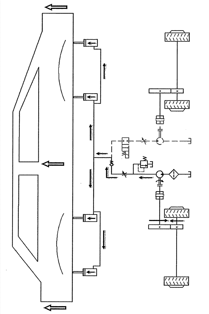
[0014] When the driver steps on the brake pedal, the braking process starts, the brake clutch 03 is engaged, the drive clutch 13 is separated, the reversing valve 11 is switched to the closed state, the rotation of the wheel is transmitted to the brake clutch through the transmission gear 02, and drives the hydraulic pump 05 rotates and starts to deliver oil to the hydraulic cylinder 09. After the hydraulic cylinder 09 is extended, the vehicle body 10 is lifted upwards, and the braking kinetic energy is converted and stored as the gravitational potential energy of the vehicle body, thereby realizing the energy recovery process. During this process, the filter 04 plays the role of cleaning the oil circuit, the overflow 08 plays the role of pres...


PUM


Abstract

The invention discloses a hydraulic brake kinetic energy recovery system for a vehicle, which is used for recycling and reusing brake kinetic energy of all kinds of vehicles, such as cars, motorcycles, electric vehicles and bicycles, and is capable of reducing energy loss of the vehicle in a running process due to frequent braking and improving the energy utilization rate. The hydraulic brake kinetic energy recovery system for the vehicle comprises a brake clutch, a hydraulic pump, a hydraulic cylinder, a hydraulic motor, a driving clutch, and an assorted one-way valve, an overflow valve, a throttle valve and a reversing valve. The technical principle is that when the vehicle brakes, an axle of the vehicle drives the hydraulic pump to convey the oil to the hydraulic cylinder through the braking clutch, after the hydraulic cylinder stretches, a vehicle body is jacked upwards, and the kinetic energy is converted to the gravitational potential energy; when the braking ends and the vehicle restarts, the dead weight of the vehicle body compresses the hydraulic cylinder to discharge the oil to the hydraulic motor, the hydraulic motor drives the driving clutch to act on the axle of the vehicle, the vehicle is driven to move forwards, and the gravitational potential energy is converted into the kinetic energy again.

Description

technical field [0001] The invention relates to a new hydraulic vehicle kinetic energy recovery system, which can be used for the recovery and reuse of braking kinetic energy of various vehicles such as automobiles, motorcycles, electric vehicles, bicycles, etc., and can reduce the energy caused by frequent braking of vehicles during driving loss and improve energy efficiency. Background technique [0002] With the continuous advancement of science and technology and the continuous improvement of residents' living standards, automobiles have become an essential travel tool for daily life. As of 2014, the number of cars in the world has reached 850 million, of which the number of cars in China has reached 260 million, and it is showing a growing trend. With the huge number of cars, the increasingly serious environmental pollution and energy shortage problems are becoming more and more prominent. How to reduce the fuel consumption and pollutant emissions of cars and realize l...

Claims


Application Information

Patent Timeline
Patent Type & Authority Applications(China)
IPC IPC(8): B60K25/00
Inventor 娄素芳赵梦龙雍平
Owner 娄素芳
Learn More