Vertical Multi-step Extrusion Die for T-shaped Parts and Its Forming Process
An extrusion die, multi-step technology, used in manufacturing tools, metal processing equipment, forging/pressing/hammer devices, etc., can solve problems such as unfavorable T-shaped parts forming, frictional resistance surface defects, and inconvenient workpiece removal. Achieve the effect of stable forming process, improving the mechanical properties of the workpiece, and reducing the cost of a single piece
- Summary
- Abstract
- Description
- Claims
- Application Information
AI Technical Summary
Problems solved by technology
Method used
Image
Examples
Embodiment 1
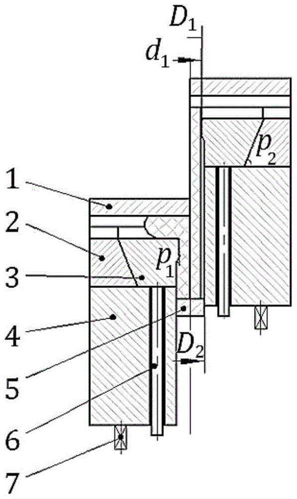
[0030] Such as image 3 As shown, this embodiment relates to an extrusion die, including: an upper die 1, a lower die 2, an inclined slider 3, a sleeve 4, a push rod 5, a push rod 6 and an elastic element 7, wherein: the upper die When mold 1, lower die 2, and inclined slider 3 are closed, a cylindrical mold cavity is formed. The sleeve 4 is controlled by the elastic element 7 to realize floating control. The concave mold is designed with a side core-pulling mechanism of the inclined slider, and the push rod 6 is set on the In the sleeve 4, the upper end is fixed on the inclined slider 3.
[0031] The diameters of the upper and lower parts of the inner side wall of the inclined slider 3 are different, and the large diameter of the upper part makes the large step of the rod part shape, and the diameter of the cavity is D 1 3.8mm, D 2 is 4.8mm, and there is a transition bevel in the middle, where the angle p 1 is 22.5°; the height of the oblique slider 3 is h=8.3mm, and the i...
Embodiment 2
[0038] The cavity diameter D in this example 1 3.9mm, D 2 is 4.9mm, and there is a transition bevel in the middle, where the angle p 1 is 23.5°; the height of the oblique slider 3 is h=8.3mm, and the inclination angle of the outer wall is p 2 = 65°.
[0039] The process steps involved in this embodiment are as follows:
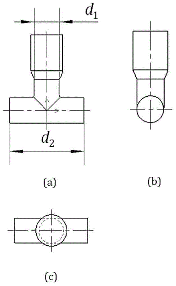
[0040] The first step is to use 20# steel to cut the material with bar, among which: the height of the bar is 32mm, the diameter is 3.8mm, and the diameter of the blank is d than the diameter of the middle rod of the connecting head 1 Smaller than 0.1mm;
[0041] The second step is forming. Put the cylindrical billet into the cavity of the extrusion mold for extrusion. The upper die, the lower die and the sleeve are pressed together by 18.5mm, so that the upper end of the workpiece is completely filled with the die cavity, and the lower end is completely filled. length d 3 Greater than the width d of the T-shaped joint step 2 , where: d 2 =11.8mm;
[...
Embodiment 3
[0044] The cavity diameter D in this example 1 4.0mm, D 2 is 5.0mm, and there is a transition bevel in the middle, where the angle p 1 is 24.5°; the height of the oblique slider 3 is h=8.3mm, and the inclination angle of the outer wall is p 2 = 63°.
[0045] The process steps involved in this embodiment are as follows:
[0046] The first step is to use 15# steel to cut the material with bar, among which: the height of the bar is 32mm, the diameter is 3.9mm, and the diameter of the blank is d 1 Smaller than 0.1mm;
[0047] The second step is forming. Put the cylindrical billet into the cavity of the extrusion mold for extrusion. The upper die, the lower die and the sleeve are pressed together by 18.5mm, so that the upper end of the workpiece is completely filled with the die cavity, and the lower end is completely filled. length d 3 Greater than the width d of the T-shaped joint step2 , where: d 2 =11.8mm;
[0048] The third step is unloading, the push rod drives the in...
PUM
 Abstract
Description
Claims
Application Information
 - R&D Engineer
- R&D Manager
- IP Professional
- Industry Leading Data Capabilities
- Powerful AI technology
- Patent DNA Extraction
Browse by: Latest US Patents, China's latest patents, Technical Efficacy Thesaurus, Application Domain, Technology Topic, Popular Technical Reports.
© 2024 PatSnap. All rights reserved.Legal|Privacy policy|Modern Slavery Act Transparency Statement|Sitemap|About US| Contact US: help@patsnap.com


