
Vacuum drying tower

A drying tower and vacuum drying technology, applied in drying, dryer, drying room/container, etc., can solve the problems of poor quality, low heat conduction and heat dissipation efficiency, long drying time, etc., so as to reduce processing costs and shorten the Drying time, the effect of rapid air extraction and dehumidification

Active Publication Date: 2017-05-24
衡阳县华盛达农林科技有限公司
View PDF15 Cites 0 Cited by
  • Summary
  • Abstract
  • Description
  • Claims
  • Application Information

AI Technical Summary

Problems solved by technology

[0002] At present, the dryers and drying towers used for drying materials on the market all use high temperature and strong wind drying. The drying process is down-flow, mixed-flow, counter-flow and combined hot air for grain drying. The whole drying process is normal pressure. There are problems such as large volume of drying equipment, low utilization rate of heat energy, high power consumption, unused waste heat, poor quality after drying, long drying time, etc.
[0003] In response to this situation, people have adopted vacuum drying technology to dry materials in vacuum at low temperature in a low-pressure vacuum state, which solves the problems of high hot air temperature and poor quality of materials after drying; All metal exhaust pipes are arranged in parallel to dissipate heat. The heat conduction and heat dissipation efficiency is low, the exhaust efficiency is low, and the vacuum degree is not well controlled, which causes the water vaporization temperature to rise, and the heat energy required for drying increases a lot, and the waste heat cannot be used.

Method used


Image

  • Vacuum drying tower
  • Vacuum drying tower
  • Vacuum drying tower

Examples


Embodiment Construction

[0035] The present invention will be further described below in conjunction with the accompanying drawings and embodiments.

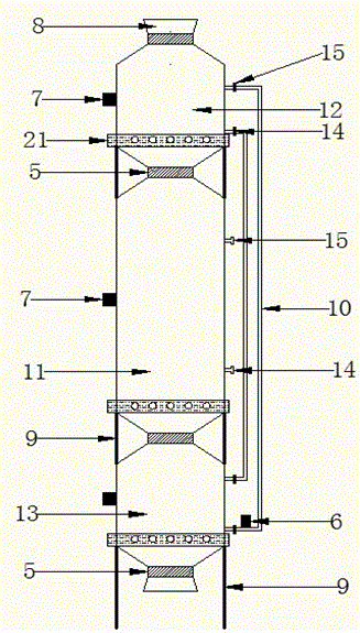
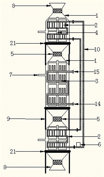
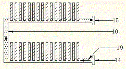
[0036] Such as figure 1 The shown vacuum drying tower consists of a vacuum drying chamber (11), a vacuum preheating chamber (12), a vacuum cooling chamber (13), a discharge valve (5), a heat pipe (10), a heat circulation pump (6), Hopper (8), bracket (9), exhaust outlet (7), heat transfer inlet (14), heat transfer outlet (15), and grain discharge device (21); the vacuum drying tower is composed of bracket (9) from bottom to top The vacuum cooling chamber (13), the vacuum drying chamber (11), and the vacuum preheating chamber (12) are fixedly installed in sequence; The material valve (5) is fixedly connected, and the vacuum cooling chamber (13), the vacuum drying chamber (11), and the vacuum preheating chamber (12) are fixedly supported by the bracket (9).

[0037] The grain discharge device (21) is installed at the lower end of the vacuum cooling bin ...


PUM


Abstract

The invention discloses a vacuum drying tower. The vacuum drying tower consists of a vacuum preheating bin, a vacuum drying bin, a vacuum cooling bin, an unloading valve, a heat conducting pipe, a heat circulating pump, a hopper, a bracket, a heat conducting inlet, a heat conducting outlet, a vacuum heat conducting cooling device, a vacuum heat exchange cooling device, an exhaust device of the vacuum drying tower and a grain discharge device, wherein a material enters the vacuum preheating bin, the vacuum drying bin and the vacuum cooling bin for respectively preheating, drying and cooling by the operation of the unloading valve through the hopper. The beneficial effects are that the exhaust device of the vacuum drying tower adopts a gap between an exhaust baffle plate and the inner wall of a bin body to achieve the effect of a gas buffer tank and the insulation effect of an insulation layer in the bin, and adopts an insulation material outside the bin body as an insulation layer, so that the temperature in the bin is not liable to drop; the heat conducting, cooling and heating speed in the bin is fast; the air exhaust and the moisture exhaust are fast; the vacuum degree in the bin is high; the moisture vaporization temperature is low; more heat energy needed by drying is reduced; more afterheat is used; the operation is simple; the drying time is shortened; the machining cost is largely reduced; the low-temperature drying guarantees the material quality; and the vacuum drying tower realizes green drying with energy conservation and emission reduction.

Description

technical field [0001] The invention relates to a drying device, in particular to a vacuum drying tower. Background technique [0002] At present, the dryers and drying towers used for drying materials on the market all use high temperature and strong wind drying. The drying process is down-flow, mixed-flow, counter-flow and combined hot air for grain drying. The whole drying process is normal pressure. There are problems such as large volume of drying equipment, low utilization rate of heat energy, high power consumption, unused waste heat, poor quality after drying, and long drying time. [0003] In response to this situation, people have adopted vacuum drying technology to dry materials in vacuum at low temperature in a low-pressure vacuum state, which solves the problems of high hot air temperature and poor quality of materials after drying; All metal exhaust pipes placed in parallel to dissipate heat, have low heat conduction and heat dissipation efficiency, low exhaus...

Claims


Application Information

Patent Timeline
IPC IPC(8): F26B17/00F26B25/06A23B9/08
CPCY02P60/85
Inventor 程长青
Owner 衡阳县华盛达农林科技有限公司
Learn More