
Bearing rolling needle and rolling column quenching machine tool

A technology for quenching machine tools and rollers, which is applied in the field of high-efficiency and energy-saving automatic quenching machine tools, can solve problems such as inability to use, and achieve the effects of low cost, consistent radial hardening layers, and high processing efficiency

Active Publication Date: 2015-06-24
SHANGHAI HEATKING INDUCTION TECH CORP
View PDF7 Cites 12 Cited by
  • Summary
  • Abstract
  • Description
  • Claims
  • Application Information

AI Technical Summary

Problems solved by technology

[0003] The high-frequency electromagnetic induction heating and quenching process has the advantages of concentrated and controllable energy, high energy utilization rate, no pollution, and convenient automatic production. It is more and more used in various industries, especially automobiles, bearings, machine tools, standard parts and other industries. However, most of the heat treatment of bearing needle rollers and rollers in standard parts is still using the quenching process of overall heating and cooling in old-fashioned electric furnaces, while for parts that require (partial) quenching of bearing needle rollers and rollers, the quenching process of overall heating obviously not available

Method used


Image

  • Bearing rolling needle and rolling column quenching machine tool
  • Bearing rolling needle and rolling column quenching machine tool
  • Bearing rolling needle and rolling column quenching machine tool

Examples


Embodiment Construction

[0037] In order to make the technical means, creative features, goals and effects achieved by the present invention easy to understand, the present invention will be further described below in conjunction with specific illustrations.

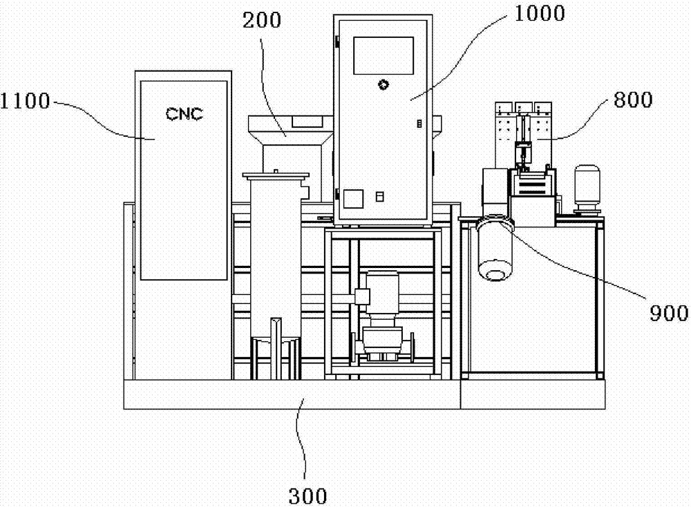
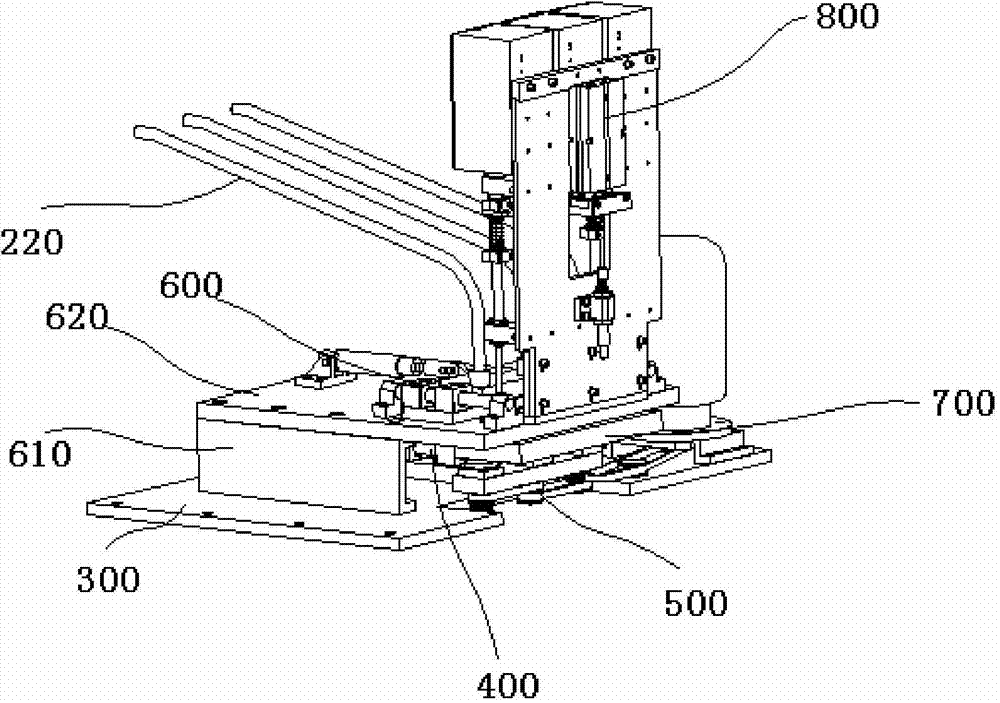
[0038] see Figure 1 to Figure 4 As shown, the invention discloses a bearing needle roller and roller quenching machine tool, which includes a feeding mechanism and a quenching mechanism. The feeding mechanism is responsible for transporting workpieces to be processed to the quenching mechanism for quenching operation.

[0039] The feeding mechanism of the present invention comprises a bed frame 100, the bed frame is welded by a steel frame, and the bed frame is stepped; at least one vibrating feeding guide mechanism 200 is provided on the top of the step, the present invention It is preferably 3 in the invention, and certainly it is also provided with more; Vibrating feeding material guide mechanism 200 comprises vibration feeding mechanism buc...


PUM


Abstract

The invention discloses a bearing rolling needle and rolling column quenching machine tool. The bearing rolling needle and rolling column quenching machine tool comprises a loading mechanism, a quenching mechanism, at least one heating inductor, a photoelectric detection mechanism, a quenching water tank discharging system, a heating and loading system and a machine tool motor numerical control system, wherein the loading mechanism comprises a bed body frame and a vibration loading and guide mechanism arranged on the bed body frame, the quenching mechanism comprises a base, a retreating and blanking mechanism arranged on the base, a workpiece positioning and rotation driving mechanism arranged on the base and a front-and-back loading sliding plate mechanism arranged above the retreating and blanking mechanism, and the vibration loading and guide mechanism is connected with the front-and-back loading sliding plate mechanism through a guide pipe; the heating inductor is arranged on the workpiece positioning and rotation driving mechanism; the photoelectric detection mechanism is arranged above the front-and-back loading sliding plate mechanism, and the photoelectric detection mechanism is responsible for detecting the existence and absence of a workpiece and the height position of the workpiece; and the quenching water tank discharging system, the heating and loading system and the machine tool motor numerical control system are arranged on the base and positioned below the heating inductor. The bearing rolling needle and rolling column quenching machine tool disclosed by the invention can automatically realize loading, unloading, heating and cooling and has no need of artificial participation.

Description

technical field [0001] The invention relates to a bearing needle roller and roller quenching machine tool, in particular to a kind of induction heating, which can heat and rapidly cool one to three bearing needle rollers and rollers at a time, so as to ensure the designated position of the bearing needle rollers / rollers A high-efficiency and energy-saving automatic quenching machine tool for quenching. Background technique [0002] Quenching machine tool, as the name implies, generally refers to the machine tool equipment that uses induction heating power supply for quenching process; it has the advantages of high precision, good reliability, time saving and labor saving; it is mainly composed of bed, sliding table, clamping and rotating mechanism, cooling system, quenching liquid circulation System, electrical control system, etc.; quenching machine tools are generally single-station (double-station quenching machine tools can be used for small-diameter workpieces); quenchi...

Claims


Application Information

Patent Timeline
Patent Type & Authority Applications(China)
IPC IPC(8): C21D9/36
Inventor 闫保宁
Owner SHANGHAI HEATKING INDUCTION TECH CORP
Learn More