
Ultrafast laser balance detection photoelectric pulse signal shaping method and realization circuit

A technology of balanced detection and signal shaping, applied in the direction of pulse shaping, etc., can solve the problems of weakening the ability of the detector to detect weak signals and reducing the signal-to-noise ratio of the detection system

Inactive Publication Date: 2017-12-01
FUDAN UNIV
View PDF5 Cites 0 Cited by
  • Summary
  • Abstract
  • Description
  • Claims
  • Application Information

AI Technical Summary

Problems solved by technology

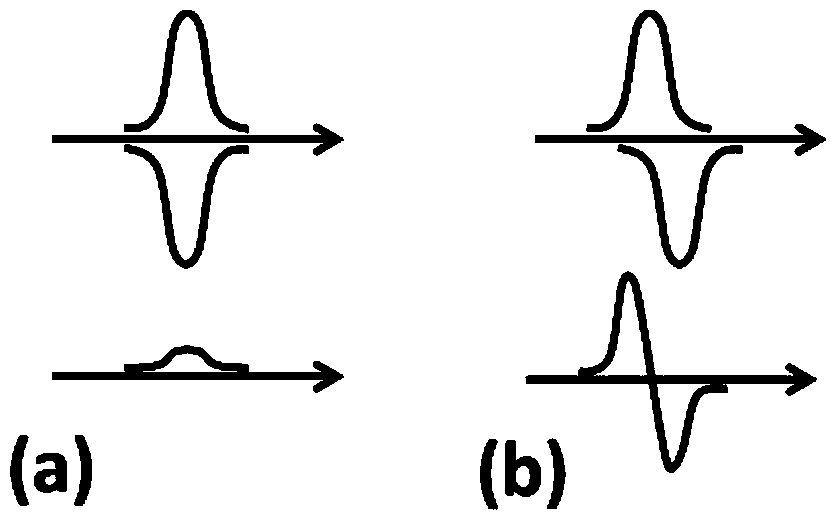
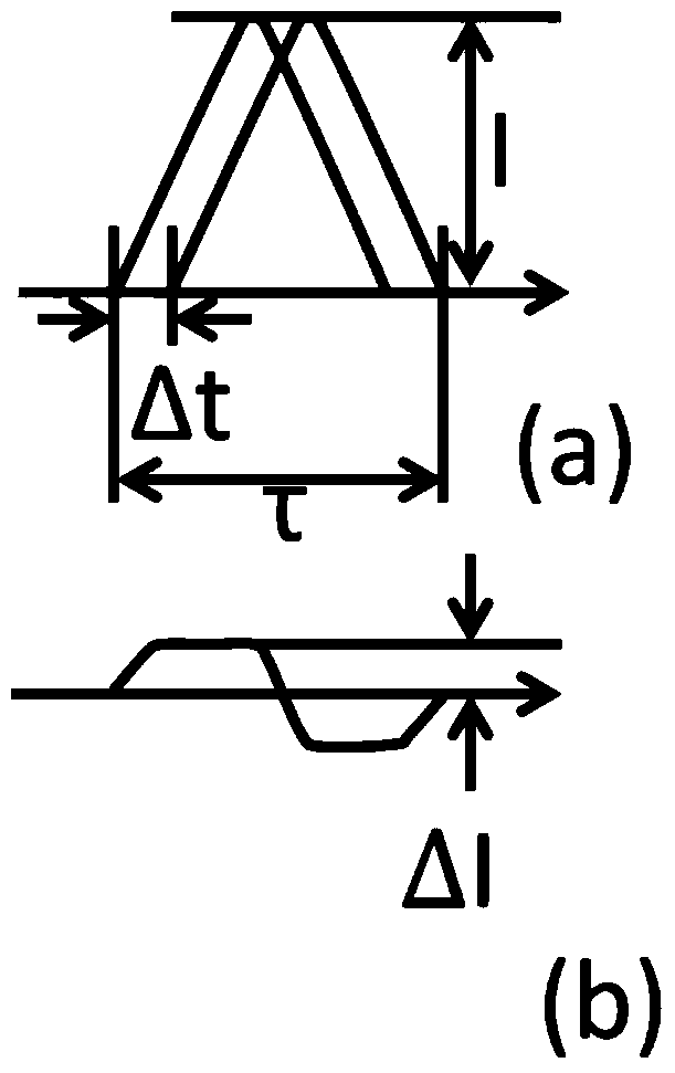
Therefore, the differential signal caused by this waveform mismatch usually accounts for a large part of the total noise, reducing the signal-to-noise ratio of the detection system
On the other hand, the differential signal formed due to waveform mismatch will largely limit the overall gain of the detector, which also weakens the detector's ability to detect weak signals

Method used


Image

  • Ultrafast laser balance detection photoelectric pulse signal shaping method and realization circuit
  • Ultrafast laser balance detection photoelectric pulse signal shaping method and realization circuit
  • Ultrafast laser balance detection photoelectric pulse signal shaping method and realization circuit

Examples


Embodiment Construction

[0022] The shaping circuit of the present invention can have multiple specific implementation modes, which are respectively introduced as follows:

[0023] 1. Implementation method A1 of the balanced detection circuit after differential first and then shaping. The circuit elements include a pair of photodiodes, an integrated operational amplifier, several resistors and capacitors, a DC power supply with positive and negative stages and grounding, as well as PCB boards, wires, and interfaces. The detection circuit is characterized in that: photodiodes are cascaded in sequence to ensure that the reverse bias is connected to the positive and negative stages of the DC power supply, and the current is drawn from between the two photodiodes to connect to a non-input circuit built by including an integrated operational amplifier. The inverting input stage of the second-order low-pass filter circuit with infinite gain of the stage resistor draws the voltage output signal from the outp...


PUM


Abstract

The invention belongs to the technical field of optical electronic devices and particularly relates to an ultrafast laser balanced detection photoelectric pulse signal shaping method and an implementation circuit. Shaping broadening processing is performed on photocurrent through an electrical means, so that differential signals caused by waveform mismatching are reduced, and the adverse effect on the balance effect is reduced. The transfer function H used by shaping broadening processing is: (imag file= 'dest_path_image 002. TIF' wi= '169' he = '24' / ), wherein s is a complex variable, (imag file= 'dest_path_image 004. TIF' wi= '23' he = '15' / ) is an inverse Laplace transformation mark, (imag file= 'dest_path_image 006. TIF' wi= '120' he = '16' / ) is a different real parameter, and the dimension is time. Various specific implementation circuits exist. The electrical shaping mode has to additional advantages of two circuits of improving the circuit high-frequency noise suppression capacity, simplifying experiment equipment, reducing the cost and improving the data accuracy and signal to noise rate.

Description

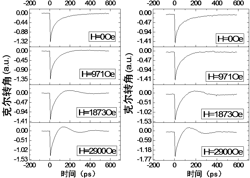
technical field [0001] The invention belongs to the technical field of optical and electronic devices, and in particular relates to a shaping method of a photoelectric pulse signal and a realization circuit thereof, which are mainly used in the balance detection of ultrafast laser pulses. Background technique [0002] Optics is a powerful means to study the properties of material materials, especially thin film materials. Optical experiments can obtain data such as optical reflectivity, transmittance, and ellipticity of materials, and based on this, we can further understand important information such as internal energy levels, electronic state pairing, and spin states. Especially with the development of ultrashort pulse laser technology at the end of the 20th century, time-resolved sub-picosecond and femtosecond pump-detection technologies emerged, but how to accurately obtain the intensity of the pulsed light after the ultrashort laser pulse interacts with matter , polari...

Claims


Application Information

Patent Timeline
Patent Type & Authority Patents(China)
IPC IPC(8): H03K5/01
Inventor 郑哲赵海斌袁昊辰郭文平
Owner FUDAN UNIV
Learn More