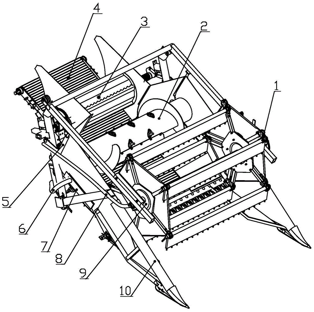
Pneumatic assisted header device for plot grain combine harvester
A combine harvester, pneumatic technology, applied in the direction of harvesters, cutters, agricultural machinery and implements, etc., can solve the problems of seed drop loss and seed grain residue on the header, achieve high material conveying efficiency and prevent mixed seeds. , The effect of saving fan energy consumption
- Summary
- Abstract
- Description
- Claims
- Application Information
AI Technical Summary
Problems solved by technology
Method used
Image
Examples
Embodiment 1
[0022] The pneumatically assisted header device of a plot grain combine harvester includes a grain divider 10, a reel assembly 1, a side baffle 13, a cutting assembly 11, a conveying device, a screw auger, a tooth plate type feeding roller 3 and a hydraulic motor. The grain divider 10 is arranged on both sides of the front end of the pneumatic assisted header device. The cutting assembly 11 is located at the bottom end of the front side of the pneumatic assisted header device, and is used for cutting straw. The conveying device is a striped belt conveying device 4, which is arranged behind the cutting assembly 21; The tooth plate type feeding roller 3 is installed at the rear end of the pneumatic assisted header device, and its outer surface is arranged with 6 wave-shaped tooth plates along the axial direction. Feed to the threshing unit. The side baffles 13 are fixed on both sides of the header device to prevent seed grains and grain ears from falling from both sides; The ...
Embodiment 2
[0025] Different from Embodiment 1, the pneumatic assisted header device also includes a lateral airflow chamber 3, which is connected to the header fan 14 through an airflow hose 16; the bottom side of the side baffle 13 Horizontal airflow hole 12 is provided, and described horizontal airflow hole 12 is connected with horizontal airflow chamber 7; The rotating air chamber cover 28 is provided with four radial passages 23 distributed along the circumference, and the radial passages 23 communicate with the split air passage 15 . The diameter of the reel 21 is 4mm, and the length is 20mm.
Embodiment 3
[0027]Different from Embodiment 2, the fixed air chamber body 27 is composed of a hollow area 25 and a solid area 26, and the hollow area 25 is provided with an air inlet 24 connected with the header fan 14, and the air inlet 24 is connected with header fan 14 by airflow hose II8. During the relative rotation of the rotating air chamber cover 28 and the fixed air chamber body 27, the radial channel 23 passes through the hollow area 25 and the solid area 26 respectively. When passing through the hollow area 25, the hollow reel 17 rotates to the In the second half of the stroke, the vertical airflow blown out during this stroke can cover the cutting deck; when passing through the solid area 26, the hollow reel 17 rotates with the eccentric reel 19 to the upper half, higher than the cutting deck, no airflow and no auxiliary airflow . The diameter of the reel 21 is 5mm, and the length is 25mm.
PUM
 Abstract
Description
Claims
Application Information
 - R&D
- Intellectual Property
- Life Sciences
- Materials
- Tech Scout
- Unparalleled Data Quality
- Higher Quality Content
- 60% Fewer Hallucinations
Browse by: Latest US Patents, China's latest patents, Technical Efficacy Thesaurus, Application Domain, Technology Topic, Popular Technical Reports.
© 2025 PatSnap. All rights reserved.Legal|Privacy policy|Modern Slavery Act Transparency Statement|Sitemap|About US| Contact US: help@patsnap.com


