
Reel assembly

A reel and component technology, applied in agricultural machinery and implements, applications, harvesters, etc., can solve the problems of seed drop loss and seed grain residue on the header, and achieve the goal of reducing the loss rate and saving the energy consumption of fans. Effect

Active Publication Date: 2015-06-24
QINGDAO AGRI UNIV
View PDF6 Cites 3 Cited by
  • Summary
  • Abstract
  • Description
  • Claims
  • Application Information

AI Technical Summary

Problems solved by technology

[0004] In order to solve the problems existing in the prior art, the present invention provides a reel assembly used in the pneumatically assisted header device of the plot grain combine harvester, which can effectively solve the problem of residual seed grains, seed grain drop loss etc.

Method used


Image

  • Reel assembly
  • Reel assembly
  • Reel assembly

Examples


Embodiment 1

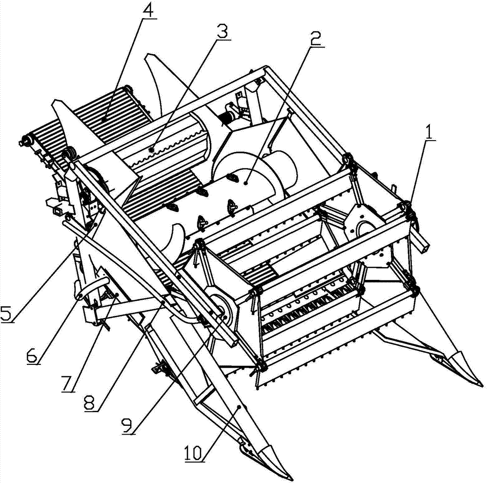
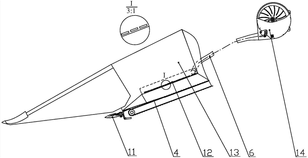
[0020] The auxiliary header device of the plot grain combine harvester includes a grain divider 10, a reel assembly 1, a side baffle 13, a cutting assembly 11, a conveying device, an auger, a toothed plate feeding roller 3 and a hydraulic motor. The grain divider 10 is arranged on both sides of the front end of the auxiliary header device. The cutting assembly 11 is located at the front bottom end of the auxiliary header device and is used for cutting straw. The conveying device is a striped belt conveying device 4, which is arranged behind the cutting assembly 11; The tooth plate type feeding roller 3 is installed at the rear end of the auxiliary header device, and its outer surface is arranged with 6 wavy tooth plates along the axial direction, the height of the tooth plates is 30-40mm, which is used to feed the harvested straw and ears without damage. into the threshing device. The side baffles 13 are fixed on both sides of the header device to prevent seed grains and ear...

Embodiment 2

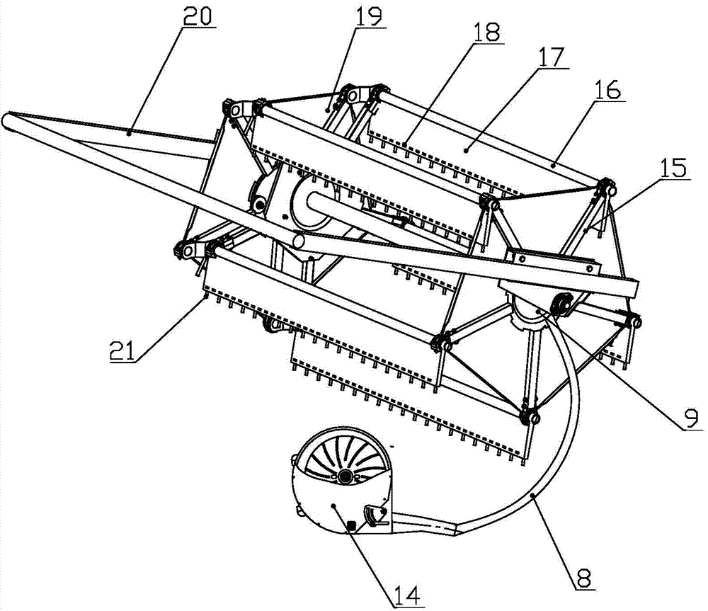
[0023] Different from Embodiment 1, the fixed air chamber body 27 is composed of a hollow area 25 and a solid area 26, and the hollow area 25 is provided with an air inlet 24 connected with the header fan 14, and the air inlet 24 is connected with header fan 14 by airflow hose II8. Since the fixed air chamber body 27 is divided into a hollow area 25 and a solid area 26, during the relative rotation of the rotating air chamber cover 28 and the fixed air chamber body 27, the radial channel 23 passes through the hollow area 25 and the solid area 26 respectively. At 25 o'clock, the hollow reel 17 rotates to the lower half with the eccentric reel 19, and the longitudinal airflow blown out in this section of the stroke can cover the cutting table; when passing through the solid area 26, the hollow reel 17 rotates with the eccentric reel 19 For the first half of the way, above the cutting deck, there is no airflow and no auxiliary airflow required.

Embodiment 3

[0025]Different from Embodiment 2, the auxiliary header device also includes a transverse airflow chamber 3, and the transverse airflow chamber 3 is connected to the header fan 14 by an airflow hose 16; the bottom side of the side baffle 13 is provided with Horizontal airflow hole 12 is arranged, and described horizontal airflow hole 12 is connected with horizontal airflow chamber 7; The rotating air chamber cover 28 is provided with four radial passages 23 distributed along the circumference, and the radial passages 23 communicate with the split air passage 15 . The diameter of the reel 21 is 4mm, and the length is 20mm.


PUM


Abstract

The invention provides a reel assembly of a cell grain harvester combine. The reel assembly comprises a cam-action reel, a hollow reel bat, a rotating air chamber assembly and a flow distributing air way. The rotating air chamber assembly is arranged on a central shaft of the cam-action reel, the rotating air chamber assembly is communicated with long branch pipes through the flow distributing air way and is further communicated with the hollow reel bat, and a longitudinal airflow hole is formed in the bottom end of one side, facing a threshing device, of the hollow reel bat. The rotating air chamber assembly comprises a fixed air chamber body and a rotating air chamber cover matched with the fixed air chamber body, the fixed air chamber body is fixed to a supporting arm, and the rotating air chamber cover rotates under driving of the central shaft of the cam-action reel. The fixed air chamber body is composed of a hollow area and a solid area, an air inlet connected with a header draught fan is formed in the solid area, and the air inlet is connected with the header draught fan through an airflow hose II. The reel assembly effectively solves the problems that seed grains are left on a header of a traditional harvester, and seed grains fall and lose.

Description

technical field [0001] The invention belongs to the field of agricultural machinery and equipment, and in particular relates to a reel assembly, in particular to a reel assembly suitable for a grain combine harvester in a community. Background technique [0002] The plot test is a field comparative test of the selected crop varieties, which is an important part of agricultural crop breeding. This link has a long operation cycle, high precision requirements, and high labor intensity. Realizing the mechanization of plot experiments can greatly improve the efficiency of breeding work, reduce the labor intensity of breeding operations, and improve operation accuracy. Compared with field harvesting, there is a big difference in crop harvesting operations in plots: (1) The area of ​​a single plot is very small; (2) Different crop varieties are planted in adjacent plots, and the seeds in the machine must be cleaned after each plot is harvested Then harvest the next plot to avoid m...

Claims


Application Information

Patent Timeline
Patent Type & Authority Applications(China)
IPC IPC(8): A01D57/02
Inventor 王家胜王东伟尚书旗王延耀胡彩旗何晓宁
Owner QINGDAO AGRI UNIV
Learn More