


Quick Research
Generate reliable direction feasibility study reports for your R&D in just a few steps.

Technical Q&A
Discover and master advanced knowledge NOW. Basics, ideas, possibilities, all at once.

Find Solutions
As an expert in R&D theories, this can generate solutions to your technical problems instantly.

Evaluate Feasibility
Analyze your overall solution with one click, know your potential R&D risks in advance.

Monitor Landscape
Get weekly tech updates, stay abreast of the latest tech innovations and key insights.
Switching power supply casing and manufacture method thereof
A technology of switching power supply and manufacturing method, which is applied in the modification of power electronics, electrical components, and output power conversion devices, etc., can solve problems such as circuit board layout limitations, and achieve the goal of reducing process complexity, increasing heat dissipation area, and simplifying manufacturing process. Effect
- Summary
- Abstract
- Description
- Claims
- Application Information
AI Technical Summary
Problems solved by technology
Method used
Image


Examples
Embodiment 1
[0054] (Example 1, the shell of the switching power supply)
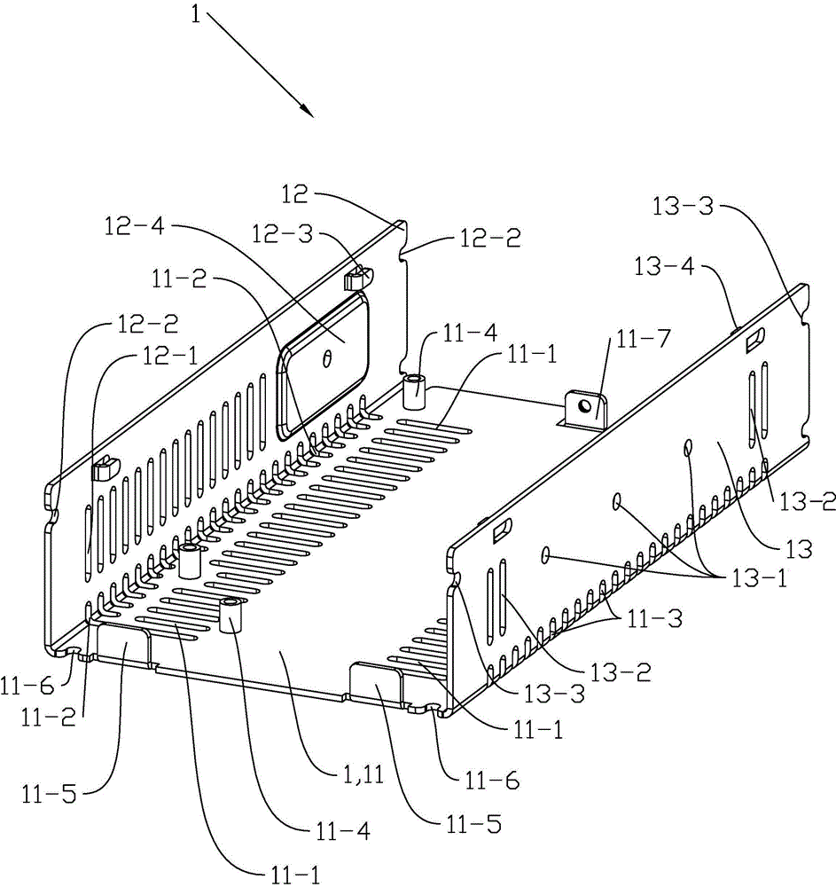
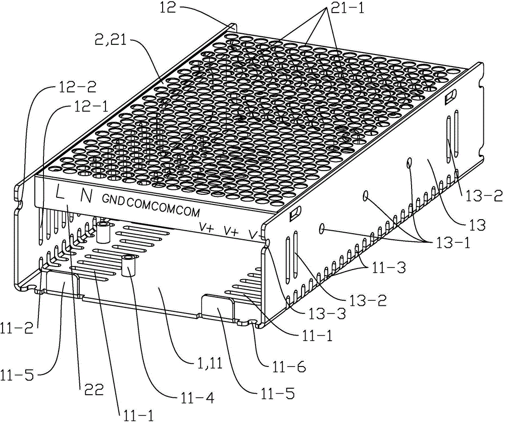
[0055] See figure 1 The shell of the switching power supply in this embodiment includes a base 1 , a cover 2 detachably mounted on the base 1 and a connecting screw, and the screw connects the base 1 and the cover 2 together. Both the base 1 and the cover body 2 are stamped parts made of aluminum or steel.
[0056] See Figure 2 to Figure 5 , the base 1 is U-shaped as a whole, including a bottom plate 11, a left side plate 12 and a right side plate 13, the bottom plate 11 is set horizontally; the left side plate 12 is vertically set, connected to the left end of the bottom plate 11 from above; the right side plate 13 is vertical Set, connected to the right end of the bottom plate 11 from above. The left and right sides of the bottom plate 11 are axially symmetrically provided with first cooling holes 11 - 1 distributed at equal intervals, and the first cooling holes 11 - 1 are waist-shaped. The connection betwee...
Embodiment 2
[0060] (Example 2, the manufacturing method of the shell of switching power supply)
[0061] The manufacturing method of the shell of the switching power supply obtained by embodiment 1 comprises the manufacturing method of the base 1 and the manufacturing method of the cover body 2 respectively, wherein the manufacturing method of the base 1 includes the following steps:
[0062] ① see Figure 10 The preliminary shape of the base 1 is formed by blanking and punching using the progressive die process: the first heat dissipation hole 11-1, the second heat dissipation hole 11-2, the third heat dissipation hole 11-3, and the first limit hole 11 of the bottom plate 11 -6, the circuit board blocking plate 11-5, the connecting plate 11-7 and the screw holes on the connecting plate 11-7, and the mounting holes of the riveted stud 11-4 have all been formed, and the mounting part 12-4 of the left side plate 12 , the second limiting hole 12-2, the left connecting foot 12-3 have been fo...
PUM
 Abstract
Description
Claims
Application Information
 - R&D Engineer
- R&D Manager
- IP Professional
- Industry Leading Data Capabilities
- Powerful AI technology
- Patent DNA Extraction
Browse by: Latest US Patents, China's latest patents, Technical Efficacy Thesaurus, Application Domain, Technology Topic, Popular Technical Reports.
© 2024 PatSnap. All rights reserved.Legal|Privacy policy|Modern Slavery Act Transparency Statement|Sitemap|About US| Contact US: help@patsnap.com