


Quick Research
Generate reliable direction feasibility study reports for your R&D in just a few steps.

Technical Q&A
Discover and master advanced knowledge NOW. Basics, ideas, possibilities, all at once.

Find Solutions
As an expert in R&D theories, this can generate solutions to your technical problems instantly.

Evaluate Feasibility
Analyze your overall solution with one click, know your potential R&D risks in advance.

Monitor Landscape
Get weekly tech updates, stay abreast of the latest tech innovations and key insights.
Miniature compression molding inductance element and manufacturing method thereof
A technology of an inductance element and a manufacturing method, which is applied in the field of miniature molded inductance elements and their manufacturing, can solve the problems of poor performance and inconvenience of automatic production of miniaturized inductance elements, and achieves the effects of flexible processing, high reliability and good consistency
- Summary
- Abstract
- Description
- Claims
- Application Information
AI Technical Summary
Problems solved by technology
Method used
Image


Examples
Embodiment 1
[0032] The miniature molded inductance element of this embodiment is suitable for mobile phones, digital cameras, computers, televisions, hard disks, set-top boxes, game machines, etc., and includes a magnetic core, a built-in coil, a magnetic molded layer and terminal electrodes, and the surface of the built-in coil is provided with Self-adhesive layer that achieves an adhesive effect after application with heat or specific solvents.
[0033] The magnetic core and the magnetic molding layer adopt ferrite or metal soft magnetic material as molding powder. The terminal electrodes include pad-printed metallization layers, electroplated metallization layers or sputtered metallization layers.
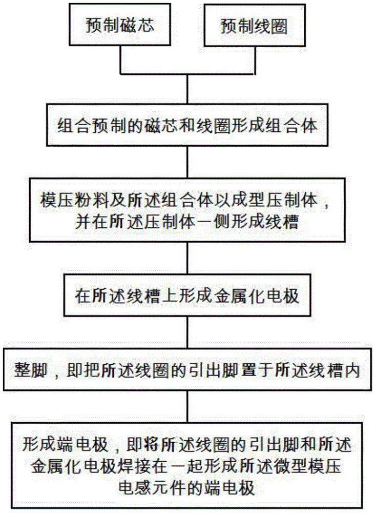
[0034] The manufacturing method of the miniature molded inductance element, such as Figure 10 shown, including the following steps:
[0035] Prefabricated magnetic core and coil: The prefabricated magnetic core step adopts molding, extrusion or cutting molding methods, and ferrite or met...
Embodiment 2
[0042] A kind of manufacturing method of miniature molded inductance element, concrete description is as follows:
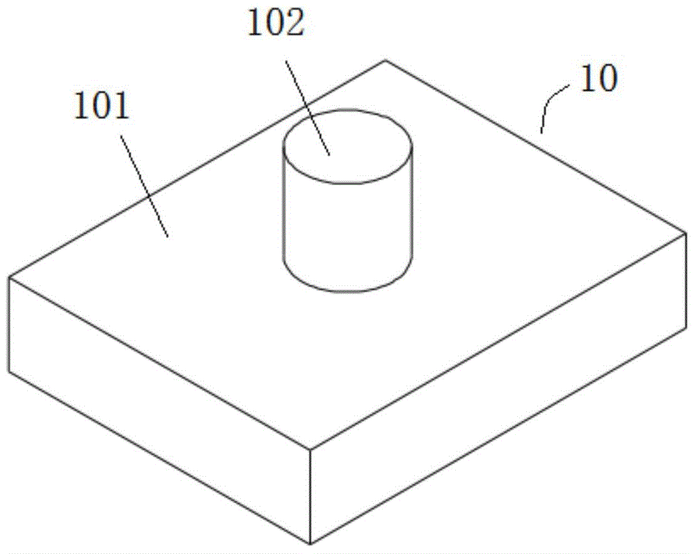
[0043] Firstly, a T-shaped magnetic core with a certain molding density is obtained by using a molding process, heated and pressurized and solidified. The T-shaped magnetic core is made of metal soft magnetic alloy, and FeSiCr powder is preferred. Such as figure 1 As shown, the prefabricated T-shaped magnetic core 10 includes a magnetic core body 101 and a core post 102 .
[0044] Made by winding machine and corresponding winding mold or other methods such as figure 2 As shown in the flat coil 20, the coil 20 includes two lead-out pins 201, and the lead-out pins 201 are drawn out after being twisted by 90° at the twisted part 202, so that the plane of the lead-out pins 201 is aligned with the electrode surface of the metallized electrode. Parallel leads. In this implementation, self-adhesive direct welding enameled wire is preferred, and the winding direction...
PUM
 Abstract
Description
Claims
Application Information
 - R&D Engineer
- R&D Manager
- IP Professional
- Industry Leading Data Capabilities
- Powerful AI technology
- Patent DNA Extraction
Browse by: Latest US Patents, China's latest patents, Technical Efficacy Thesaurus, Application Domain, Technology Topic, Popular Technical Reports.
© 2024 PatSnap. All rights reserved.Legal|Privacy policy|Modern Slavery Act Transparency Statement|Sitemap|About US| Contact US: help@patsnap.com