Hydraulic valve bonnet manufacturing process
What is Al technical title?
Al technical title is built by PatSnap Al team. It summarizes the technical point description of the patent document.
A manufacturing process and technology for hydraulic valves, applied in valve devices and other directions, can solve problems such as easy oil leakage, high cost, and reduced mechanical properties, and achieve the effects of stable dimensional accuracy, high mechanical strength, and reduced probability of oil leakage.
Active Publication Date: 2017-07-11
JIANGSU LONGCHENG PREC FORGING CO LTD
View PDF6 Cites 0 Cited by
Summary
Abstract
Description
Claims
Application Information
AI Technical Summary
This helps you quickly interpret patents by identifying the three key elements:
Problems solved by technology
Method used
Benefits of technology
Problems solved by technology
The blank produced by the traditional casting process has the following defects: there are a large number of casting defects such as pores and porosity inside the casting blank, which leads to a great reduction in its mechanical properties in all aspects, and oil leakage is prone to occur during use; in addition, the cost of machining is relatively high
Method used
Image
Click on the blue label to locate the original text in one second.
Reading with bidirectional positioning of images and text.
Examples
Embodiment Construction
[0037] The present invention is described in further detail now in conjunction with accompanying drawing. These drawings are all simplified schematic diagrams, which only illustrate the basic structure of the present invention in a schematic manner, so they only show the configurations related to the present invention.
[0038] Such as Figure 3-11 Shown, a kind of hydraulic valve bonnet manufacturing process of the present invention, comprises steps as follows,
[0039] a. Cutting: Prepare the required raw materials according to the weight and size, specifically, cut the 45# hot-rolled round bar into raw materials.
[0040] b. Heating: The raw materials are heated in a heating furnace, the temperature in the heating furnace is 1050-1100°C, and the heating furnace is an intermediate frequency induction heating furnace.
[0041] c. Upsetting: Put the heated raw material into the upsetting mold for upsetting to form a blank, and remove the oxide skin on the surface of the blan...
PUM
Abstract
The invention relates to a hydraulic valve cover manufacturing process. The process includes the following steps of a, discharging, wherein the required raw material is prepared according to weight and size, b, heating, wherein heating is conducted on the raw material in a heating furnace, c, upsetting, wherein the heated raw material is placed in an upsetting die, unsetting is conducted on the raw material to form a workblank, and the oxide skin on the surface of the workblank is removed; d, dummying, wherein performing is conducted on the workblank generated after the oxide skin is removed to form a pre-forging piece, e, precision forging, wherein fine machining is conducted on the preformed workblank to form a precision forging piece, f, burr cutting, wherein burrs of the precision forging piece are cut on a punching machine, g, normalizing, wherein the precision forging piece generated after burr cutting is conducted is placed in a furnace, and normalizing is conducted on the precision forging piece, h, shot blasting, wherein the oxide skin on the surface of the precision forging piece generated after normalizing is conducted is removed and i, cold sizing, wherein local cold sizing is conducted on the precision forging piece on a cold forging machine. According to the hydraulic valve cover manufacturing process, the workblank is formed through hot forging, then cold-extrusion is conducted on a key face, the plane degree and parallel degree are guaranteed, traditional machinery machining is replaced, the production cost is saved, and the forged piece is high in mechanical strength and stable in size accuracy.
Description
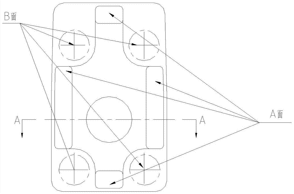
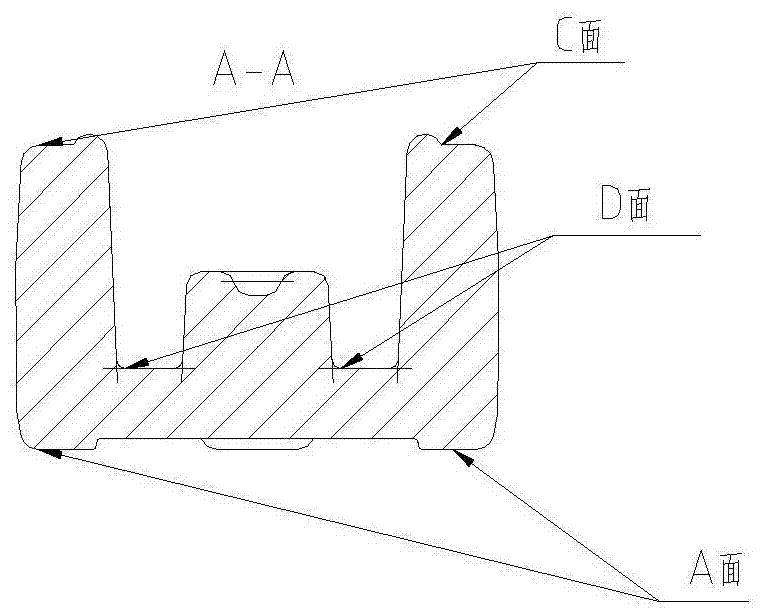
technical field [0001] The invention relates to a manufacturing process of a valve cover of a hydraulic valve. Background technique [0002] The bonnet of the hydraulic valve is a part of the industrial hydraulic system, and its dimensional accuracy is very high due to assembly requirements; such as figure 1 and figure 2 , Surface B is the final bolt fastening surface of the valve cover. To ensure the sealing performance after assembly, the parallelism between surface B and surface A is required to be within 0.1, and the flatness of surface B is required to be within 0.05; surface C is the surface between the valve cover and the valve. The fitting surface of the body, the flatness of the C surface must be within 0.02, otherwise there will be a risk of oil leakage. Surface A is the reference plane for subsequent machining of surface C, so the flatness requirements of this surface must be guaranteed first, otherwise the flatness requirements of surface C cannot be guarantee...
Claims
Application Information
Patent Timeline
Application Date:The date an application was filed.
Publication Date:The date a patent or application was officially published.
First Publication Date:The earliest publication date of a patent with the same application number.
Issue Date:Publication date of the patent grant document.
PCT Entry Date:The Entry date of PCT National Phase.
Estimated Expiry Date:The statutory expiry date of a patent right according to the Patent Law, and it is the longest term of protection that the patent right can achieve without the termination of the patent right due to other reasons(Term extension factor has been taken into account ).
Invalid Date:Actual expiry date is based on effective date or publication date of legal transaction data of invalid patent.