Row-depth-variable fin heat exchanger

A finned heat exchanger and fin technology, applied in the field of air source heat pump air conditioning units, can solve the problem that frost formation on the surface of the fins and outside the heat exchange tubes cannot be effectively improved, increase the air resistance of the heat exchange tubes, and prevent the refrigerant side tubes from Shorten the process and other issues, to achieve the effect of reducing material consumption, improving heat exchange effect, and easy processing and manufacturing

Inactive Publication Date: 2015-05-06
TIANJIN UNIV OF COMMERCE
View PDF7 Cites 2 Cited by
  • Summary
  • Abstract
  • Description
  • Claims
  • Application Information

AI Technical Summary

Problems solved by technology

But doing so will greatly increase the complexity of the equipment and the structural size of the whole machine while improving the uneven air distribution, and also increase the air resistance outside the heat exchange tube; the patent publication number is CN2605537Y, and the invention name is "A Wind In the patent literature of Finned Heat Exchanger for Cold and Heat Pumps, it is proposed to divide the refrigerant side of the heat exchanger into several tubes, so that the tubes on the refrigerant side with smaller wind speeds are lengthened, and the tubes on the refrigerant side with higher wind speeds are longer. shorten
This can partially improve the heat transfer effect in the longer tube pass area, but it reduces the efficiency of the fins, and the frosting on the surface of the fins and the outside of the heat exchange tubes in the small wind speed area cannot be effectively improved

Method used


Image

  • Row-depth-variable fin heat exchanger
  • Row-depth-variable fin heat exchanger
  • Row-depth-variable fin heat exchanger

Examples


Embodiment Construction

[0014] The present invention will be described in further detail below in conjunction with the accompanying drawings and specific embodiments.

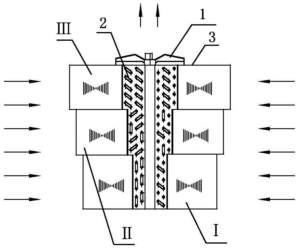
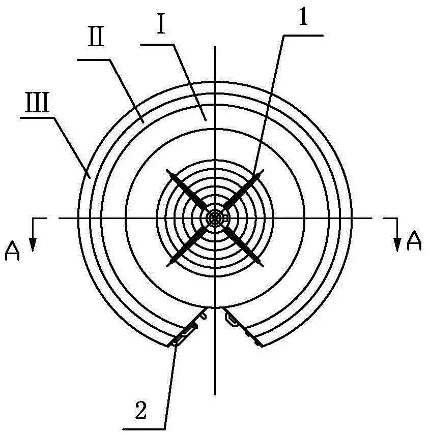
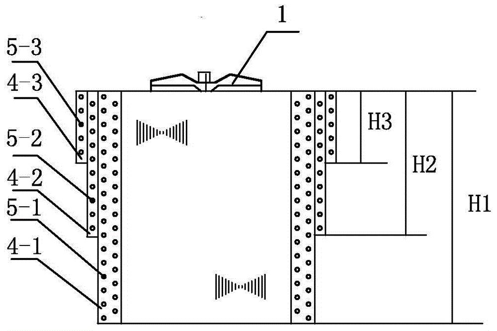
[0015] The variable row deep fin heat exchanger of the present invention includes a plurality of heat exchange units, each of which consists of a plurality of heat exchange tubes and a set of heat exchange tubes sleeved on the heat exchange tubes. Each of the heat exchange tubes is circular with an opening, and a plurality of the heat exchange tubes are connected through an elbow at the opening and are provided with a refrigerant inlet and a refrigerant outlet. The lengths are basically equal, the refrigerant inlet of each heat exchange unit is respectively connected to the inlet collection main pipe, and the refrigerant outlet of each heat exchange unit is respectively connected to the outlet collection main pipe; multiple heat exchange units are assembled to form Concentric fan-shaped; the heat exchange units are arranged concentric...


PUM


Abstract

The invention discloses a row-depth-variable heat exchanger and provides a fin tube heat exchanger which is used for improving uneven face velocity of the heat exchanger and relieving frosting of an area in a long distance away from an air inlet of a fan. The row-depth-variable heat exchanger comprises a plurality of heat exchange units, wherein each heat exchange unit comprises a plurality of heat exchange tubes and a group of fins which sleeve the heat exchange tubes; each heat exchange tube is in a shape of a circle with an opening; openings of the heat exchange tubes of each heat exchange unit are connected through an elbow, and each heat exchange tube is provided with a refrigerant inlet and a refrigerant outlet; the multiple heat exchange units are assembled to form a concentric fan shape, are arranged from inside to outside and are concentrically arranged; the fan is arranged at the upper part of an overall top sealing plate; the center of the fan is concentric to the multiple heat exchange units; the height of fins of each heat exchange unit is gradually reduced or increased from inside to outside in the horizontal direction; the fins of each heat exchange unit are equal in distance away from the air inlet of the fan on the same contour plane; the number of rows of the heat exchange tubes is reduced while the number of the heat exchange units is reduced along with the increase of the distance away from the air inlet of the fan in the vertical direction.

Description

technical field [0001] The invention relates to the technical field of air-source heat pump air-conditioning units, and more specifically relates to a variable-row deep fin tube heat exchanger for air-source heat pump air-conditioning units. Background technique [0002] The air source heat pump air conditioner has been widely used because of its convenient installation, no need for cooling water and high heat exchange efficiency, and the finned heat exchanger is a main heat exchange element of the air source heat pump air conditioner. Usually the heat exchanger is a square, and the refrigerant coming out of the throttle valve is evenly distributed into each tube side of the heat exchanger, and the length of the heat exchange tubes of each tube side is the same, and the row depth of the heat exchanger from top to bottom is the same. Under the action of the fan, the air passes over the surface of the heat exchanger to complete heat exchange with the refrigerant in the heat ex...

Claims


Application Information

Patent Timeline
Patent Type & Authority Applications(China)
IPC IPC(8): F25B39/00
CPCF25B39/00F25B2347/00
Inventor 郭宪民汪伟华
Owner TIANJIN UNIV OF COMMERCE
Why Eureka
Try Eureka