
Temperature sensor array structure based on tetragonal lattice dielectric post photonic crystal

A technology of temperature sensor and photonic crystal, which is applied to thermometers, thermometers, instruments, etc. with physical/chemical changes. It can solve the problems of narrow band gap, affect integration, and low sensor sensitivity, and achieve low power consumption and accurate detection. High performance and simple structure

Active Publication Date: 2015-04-29
BEIJING UNIV OF POSTS & TELECOMM
View PDF6 Cites 10 Cited by
  • Summary
  • Abstract
  • Description
  • Claims
  • Application Information

AI Technical Summary

Problems solved by technology

For example (document 6, S.Mandal and D.Erickson, "Nanoscale optofluidic sensor arrays," Optics Express 16(3), 1623–1631, (2008)), a biological sensor composed of many photonic crystals with single rows of holes was designed. Molecular sensor array, but the sensor array is not implemented on the same photonic crystal flat panel module, which affects the integration level
Through improvement, (Document 7, D.Yang, H.Tian, ​​and Y.Ji, "Nanoscale photonic crystal sensor arrays on monolithic substrates using side-coupled resonant cavity arrays," Optics Express 19(21), 20023–20034, ( 2011)), a photonic crystal refractive index sensor array was designed by using side cavity coupling, which greatly improved the integration level. However, the sensor array structure is based on triangular lattice air-hole photonic crystals, which has a narrow band gap and low sensor sensitivity.

Method used


Image

  • Temperature sensor array structure based on tetragonal lattice dielectric post photonic crystal
  • Temperature sensor array structure based on tetragonal lattice dielectric post photonic crystal
  • Temperature sensor array structure based on tetragonal lattice dielectric post photonic crystal

Examples


Embodiment Construction

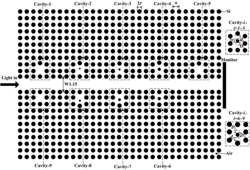
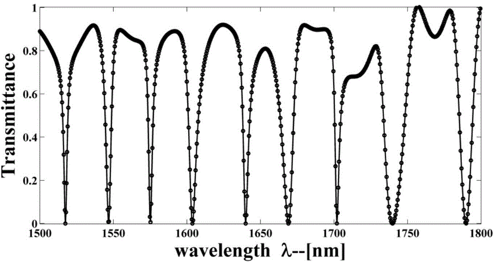
[0036] The structural model of the photonic crystal temperature sensor array of the tetragonal lattice dielectric column is as follows: figure 1 As shown, it contains a W1.15 photonic crystal waveguide and 9 highly efficient coupled photonic crystal resonators. The resonant cavity is composed of 9 adjacent dielectric columns, where the radius of the functional dielectric column is r i , the corresponding displacement is D i , the displacement of the medium column above the functional medium column is d i ;Lattice constant a=600nm, other dielectric column radius r=108nm, the refractive index of background air medium is 1.0, and the refractive index of dielectric column silicon is n si = 3.4. When the structural parameter r of the resonator i ,D i , d i When any one of the parameters changes, the resonant frequency of the resonant cavity will change accordingly. Therefore, the basic structure of the photonic crystal temperature sensor array can be formed by rationally des...


PUM


Abstract

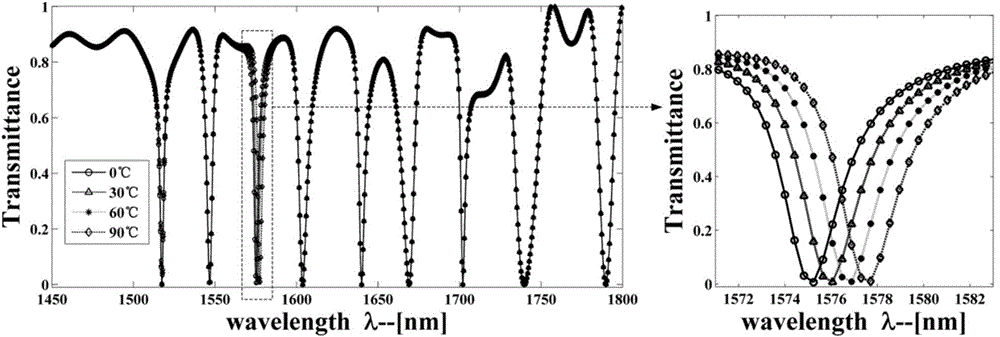
The invention relates to a temperature sensor array structure formed by coupling a tetragonal lattice dielectric post photonic crystal W1.15 waveguide and nine single-hole microcavities, and belongs to the technical field of photonic crystal sensors. According to the method, a tetragonal lattice dielectric post photonic crystal array structure is firstly applied to the design of temperature sensors, the number of the temperature sensors on the same module is increased, high temperature sensitivity is obtained, and accordingly detection accuracy of a temperature sensor array is greatly improved. The nine single-hole microcavities are coupled in the vertical direction of the W1.15 waveguide, and resonance frequencies of the nine microcavities are different. When temperature around the certain microcavity of the photonic crystal temperature sensor array changes differently, the resonant wavelength of the microcavity deviates differently, and harmonic peaks of other microcavities are kept unchanged, namely, the microcavities can achieve the sensing function independently and do not interfere with one another. The photonic crystal sensor array structure has extendibility and can be used for temperature sensing at the same time.

Description

technical field [0001] The invention relates to a method for realizing a temperature sensor array formed by coupling a W1.15 waveguide of a tetragonal lattice dielectric columnar photonic crystal with nine single-hole microcavities, and belongs to the technical field of photonic crystal sensors. Background technique [0002] Since the photonic crystal was proposed in the 1980s, it has been widely used in modulation, filtering and sensing due to its good photon band gap and photon localization characteristics. Photonic crystal sensors have shown great advantages and potentials in the field of sensors due to their high sensitivity, small size, and low power consumption. At present, research on photonic crystal sensors is mainly focused on biochemical sensors (Document 1, W.Lai, S.Chakravarty, Y.Zou, Y.Guo, and R.T.Chen, “Slow light enhanced sensitivity of resonance modes in photonic crystal biosensors,” Applied Physics Letters 102(4), 041111, (2013)), pressure sensor (documen...

Claims


Application Information

Patent Timeline
Patent Type & Authority Applications(China)
IPC IPC(8): G01K11/00
Inventor 田慧平张攀周健杨大全黄利军纪越峰
Owner BEIJING UNIV OF POSTS & TELECOMM
Learn More