
Forced pressing type wire drawing machine with wire swing mechanism

A technology of forced pressing and wire drawing machine, which is applied to the production of complete sets of equipment for artificial threads, textiles and papermaking, etc. It can solve problems such as laborious, inability to separate free water, and feed blockage

Active Publication Date: 2016-09-07
NINGBO LVHUA RUBBER & PLASTIC MACHINERY IND & TRADE
View PDF4 Cites 0 Cited by
  • Summary
  • Abstract
  • Description
  • Claims
  • Application Information

AI Technical Summary

Problems solved by technology

[0003] The first object of the present invention is to provide a forced pressing type wire drawing machine with a wire swing mechanism that can accelerate the cooling of the plastic wire, save labor when pushing the material forward in the barrel, and is not easy to cause feed blockage. It solves the problem that the existing plastic wire drawing machine is cooled by natural cooling, the cooling time is long, the material is laborious when pushing the material forward in the barrel, and the problem of feeding blockage is easy to occur
[0004] The second purpose of the present invention is to further provide a forced pressing type wire drawing machine with a wire-swing mechanism that can feed plastics in a closed manner and separate free water from plastic raw materials. Oxidation is easy to occur during the feeding process, resulting in broken wires and the inability to separate the free water in the plastic

Method used


Image

  • Forced pressing type wire drawing machine with wire swing mechanism
  • Forced pressing type wire drawing machine with wire swing mechanism
  • Forced pressing type wire drawing machine with wire swing mechanism

Examples


Embodiment 1

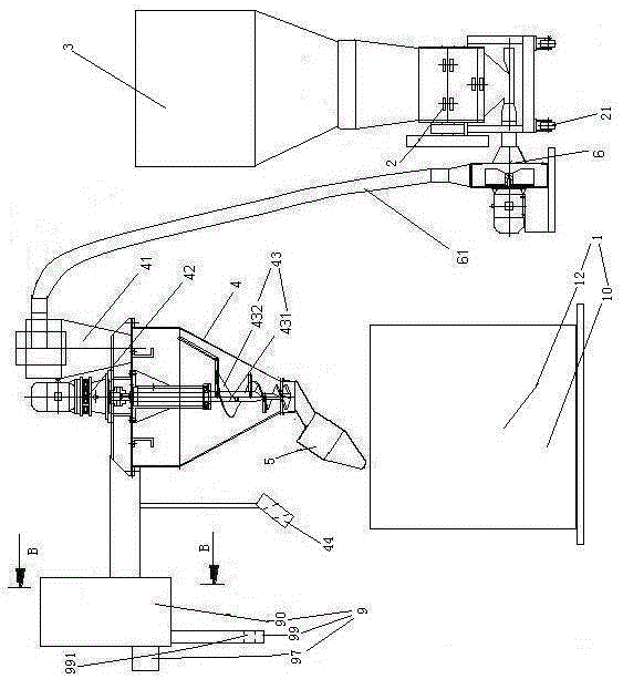
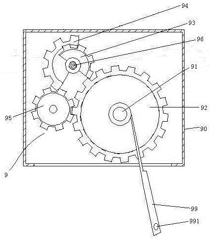
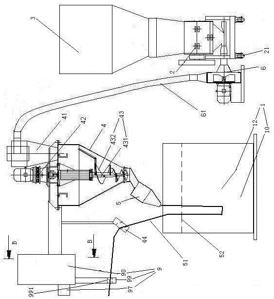
[0045] Embodiment one, see figure 1 , a forced pressing type wire drawing machine provided with a wire swing mechanism, including a feed barrel 3, a pulverizer 2, a feeding fan 6, a barrel 4, a die head 5, a cooling mechanism 1 and a wire swing mechanism 9.

[0046] The pulverizer 2 is provided with road wheels 21 . The feeding bucket 3 is located above the pulverizer 2 . Feeding barrel 3 is a funnel structure. The lower end of the feeding barrel 3 is connected with the inlet end of the pulverizer 2 . The discharge end of the pulverizer 2 is connected with the inlet end of the feeding fan 6, specifically, it is detachably connected together by screws. The outlet end of feeding fan 6 is connected together with the lower end of riser pipe 61. The upper end of the riser 61 is connected with the feed end of the material splitter 41 . The barrel 4 is in an upright state. The lower end of the barrel 4 is higher than the pulverizer 2 . The material splitter 41 is arranged on t...

Embodiment 2

[0053] Embodiment two, the difference with embodiment one is:

[0054] see Figure 4 , also includes a water pump 7 and a nozzle 8. The feed bucket 3 includes an outer tank body 31 , an inner tank body 32 and an isolation floating plate 33 .

[0055] The outer tank body 31 has an open upper end structure. The upper end of the outer tank body 31 is provided with a water inlet pipe 311 . A water inlet valve 312 is disposed in the water inlet pipe 311 . The lower end of the outer tank body 31 is provided with a drain pipe 313 . A drain valve 314 is provided in the drain pipe 313 . A supporting frame 315 is arranged inside the outer tank body 31 .

[0056] The inner tank body 32 is a structure with a lower end, that is, an open bottom end. The inner tank body 32 is connected to the supporting frame 315 and suspended in the outer tank body 31 . The top of the inner tank body 32 is provided with a material inlet 321 and a material outlet 322 . A feed valve 323 is provided i...

Embodiment 3

[0065] Embodiment three, the difference with embodiment two is:

[0066] see Figure 10 The cooling mechanism 1 also includes a support shaft 11 , a drive motor 13 , a thermostat 14 , a circulation pump 15 , a water removal mechanism 16 , a support seat 17 , a vacuum generator 18 and a control valve 19 .

[0067] The support shaft 11 is in an inclined state. The support shaft 11 is rotatably connected to the base 10 . The support shaft 11 is provided with several driving wheels 111 distributed along the axial direction.

[0068] The cooling bucket 12 is circular.

[0069] The thermostat 14 is fixed on the base 10 . The outlet of the thermostat 4 is provided with an outlet pipe 141 extending into the cooling bucket 12 .

[0070] The circulation pump 15 is fixed on the base 10 . The inlet of the circulating pump 15 is connected with a water inlet pipe 151 extending into the cooling water bucket 12 . The outlet of circulation pump 15 is connected together with the inlet of...


PUM


Abstract

The invention relates to a plastic wire drawing machine. The reinforced compression type wire drawing machine provided with a wire swaying mechanism comprises a vertical material cylinder, a die head, a crusher, a compressing screw rod, a cooling water barrel and the wire swaying mechanism, wherein the compressing screw rod is positioned in the material cylinder; the cooling water barrel is positioned below the die head; an outlet end of the crusher is connected with the upper end of the material cylinder. The reinforced compression type wire drawing machine has the advantages that the cooling speed of a plastic wire can be increased, labor is saved when a material is pushed to move forwards in the material cylinder, and the phenomenon that the fed material blocks is not easy to cause; the problems that the cooling time is long, a worker feels laborious when the material is pushed to move forwards in the material cylinder, and the phenomenon that the fed material blocks is easy to cause when the current plastic wire drawing machine adopts a natural cooling way for cooling are solved.

Description

technical field [0001] The invention relates to a plastic wire drawing machine, in particular to a forced pressing type wire drawing machine provided with a wire swing mechanism. Background technique [0002] Plastic wire drawing machine is a device for making plastic into plastic wire. A kind of plastic wire drawing machine is disclosed in the patent document that the Chinese patent application number is 012290475, the publication date is March 6, 2002, and the name is "exhaust-free energy-saving plastic wire drawing machine". The plastic wire drawing machine includes a pressing mechanism and a die head, and the pressing mechanism includes a feeding barrel and a barrel. When in use, the plastic raw material is poured into the feed barrel, and then enters the barrel through the feed barrel, and is heated and melted by the melting machine for related processing when passing through the barrel, and then output through the die to form a plastic filament. The existing plastic ...

Claims


Application Information

Patent Timeline
Patent Type & Authority Patents(China)
IPC IPC(8): D01D13/02D01D5/088
CPCD01D5/088D01D13/02
Inventor 诸豪
Owner NINGBO LVHUA RUBBER & PLASTIC MACHINERY IND & TRADE
Learn More