
Three-dimensional cavitation quantitative imaging method for microsecond-distinguished cavitation time-space distribution

A space-time distribution and imaging method technology, applied in image enhancement, material analysis, image analysis, etc., can solve problems such as asymmetry, inapplicability to in-situ research, and inability to reflect cavitation intensity distribution

Active Publication Date: 2015-04-22
XI AN JIAOTONG UNIV
View PDF4 Cites 14 Cited by
  • Summary
  • Abstract
  • Description
  • Claims
  • Application Information

AI Technical Summary

Problems solved by technology

Optical detection imaging mainly includes high-speed / ultra-high-speed photography, sonoluminescence and sonochemiluminescence, etc., which can be used to observe the behavior of cavitation bubbles and the dynamic characteristics of space and time. It has the advantages of intuition, good synchronization, and high time resolution. On the one hand, it has high requirements on the light transmittance of the medium and is not suitable for in-situ research; on the other hand, the obtained image is the superposition of information along the direction of light penetration
The current cavitation quantification methods mainly include inertial cavitation dose and non-inertial cavitation dose, which calculate the root mean square value of broadband noise or sub-harmonic amplitude in a specific frequency band as a relative measure of cavitation intensity, which can be measured separately The relative size of transient cavitation and steady-state cavitation, but generally for the one-dimensional radio frequency data collected by PCD, this quantification method cannot reflect the distribution of cavitation intensity
The existing cavitation density detection method is the laser phase Doppler method. This method is mainly aimed at the distribution of cavitation bubbles in different sizes, but the density distribution of cavitation bubbles in different spatial positions has not been studied, and it cannot provide spatial information.
[0006] At present, the existing cavitation detection and imaging methods are limited to one-dimensional and two-dimensional, and the distribution area of ​​the actual hollow cavitation bubbles spreads over the entire focal area or even larger, and in clinical applications such as focused ultrasound therapy, there may be Other tissue media make the sound field distribution change and cause asymmetry, so it is necessary to develop a microsecond-resolution three-dimensional space-time distribution imaging of cavitation and quantitative imaging method of cavitation microbubble density

Method used


Image

  • Three-dimensional cavitation quantitative imaging method for microsecond-distinguished cavitation time-space distribution
  • Three-dimensional cavitation quantitative imaging method for microsecond-distinguished cavitation time-space distribution
  • Three-dimensional cavitation quantitative imaging method for microsecond-distinguished cavitation time-space distribution

Examples


Embodiment 1

[0076] Example 1. Taking medium tap water as an example, the pulse length of high-intensity focused ultrasound is 10us-200ms, and the electric power is 100W. Cavitation and cavitation density quantitative three-dimensional imaging of cavitation bubbles generated under the experimental conditions:

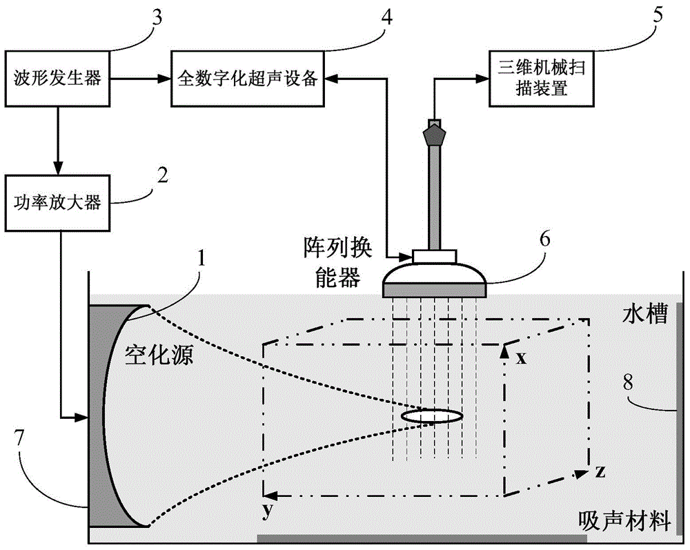
[0077] (1) use figure 1The experimental device, tap water is injected into the water tank, the high-intensity focused ultrasonic transducer is fixed on the side wall of the water tank, the Sonix-Touch full-digital ultrasonic device is used to emit a wide beam to detect cavitation microbubbles, and the array transducer propagates along the high-intensity focused ultrasonic wave The direction is placed so that its central position corresponds to the focal area of ​​the high-intensity focused ultrasound transducer, and the synchronization between the two is realized by the dual-channel arbitrary waveform generator AWG420;

[0078] (2) Set the pulse length of high-intensity focused ultr...

Embodiment 2

[0084] Embodiment 2. Under the condition of pulsating flow, the pulse length of high-intensity focused ultrasound is 20us, the electric power is 100W, the pulsation frequency is 80 times / second, the flow velocity is 5cm / s, and the pipeline diameter is 4mm. Quantitative 3D imaging of cavitation and cavitation density:

[0085] (1) Prepare agar gelatin imitation vascular tissue phantom, mix agar (3%), gelatin (12%) and degassed water (85%), heat and stir until completely dissolved, put in a degassing box for 30 minutes, pour After entering the mold and waiting for cooling and solidification, slowly pull out the tube to form a pipeline. The two ends of the pipeline are connected with latex tubes and connected to a pulsating pump. The pulsating pump flows the liquid from the storage tank through the pipeline into the waste liquid pool, forming a pulsating flow in the pipeline.

[0086] (2) adopt Figure 4 The experimental device, tap water is injected into the tank, the high-inte...


PUM


Abstract

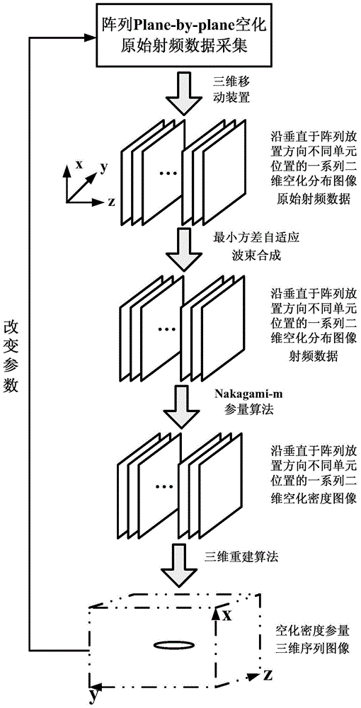
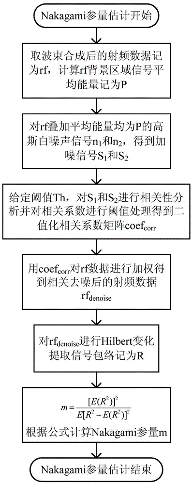
The invention provides a three-dimensional cavitation quantitative imaging method for microsecond-distinguished cavitation time-space distribution. The three-dimensional cavitation quantitative imaging method comprises the following steps: after wide beams are used for detecting the cavitation, an array transducer is moved by one unit position; after the cavitation-nucleus distribution is restored, and under the excitation of same cavitation energy, the wide beams are reused for detecting the cavitation, space-series two-dimensional cavitation original radio-frequency data with different unit positions is obtained; time-sequence two-dimensional cavitation original radio-frequency data can be obtained by changing the energy acting time of a cavitation source, the time delay between the excitation of an energy source device and the wide beams transmitted by the array transducer and the time delay between a pulsating pump and excitation of the energy source device; then a microsecond-distinguished cavitation three-dimensional time-space distribution image and a quantitative image of cavitation microbubble density can be obtained by combining minimum-variance self-adaptive beam synthesis of the wide beams, Nakagami parameter imaging and a three-dimensional reconstruction algorithm, and the time resolution can reach microseconds. The method has the potential of being developed into a standard three-dimensional cavitation imaging method similar to soundfield measurement.

Description

technical field [0001] The invention relates to the field of cavitation physics and application and ultrasonic imaging technology. The method combines array Plane-by-plane wide-beam cavitation detection, wide-beam minimum variance adaptive beam synthesis and Nakagami parameter imaging algorithm to realize steady-state free field and pulsation Microsecond resolution imaging of three-dimensional space-time distribution of cavitation and quantitative imaging of cavitation microbubble density under flow conditions. Background technique [0002] Cavitation refers to the activation of cavitation nuclei in liquids under the action of external energy (heat / force), and a series of dynamic processes such as oscillation, growth, shrinkage and even collapse of micro-bubble nuclei occur. , gene transfection, in vitro lithotripsy, thrombolysis, hemostasis, hyperthermia, and tumor thermal ablation. The process of cavitation includes the following stages: cavitation nucleation, linear and ...

Claims


Application Information

Patent Timeline
Patent Type & Authority Applications(China)
IPC IPC(8): G01N29/02
CPCG01N29/0654G01N29/265G01N2291/02433G01N2291/106G01N29/02G06T5/00G06T7/0012G06T7/60G06T11/008G06T2200/04G06T2207/10136G06T2207/20182
Inventor 万明习丁婷胡虹杨淼郭世放
Owner XI AN JIAOTONG UNIV
Learn More