
Synchronous multi-point ignition center core igniter

A fire pipe and multi-point technology is applied in the field of artillery propellant charge ignition system, which can solve the problems of insufficient flame propagation speed of common ignition agents, inability of each hole to spray fire at the same time, and unfavorable artillery weapon safety. The effect of shortening the overall combustion time, improving ignition simultaneity, and improving ignition reproducibility

Inactive Publication Date: 2015-04-22
XIAN MODERN CHEM RES INST
View PDF6 Cites 5 Cited by
  • Summary
  • Abstract
  • Description
  • Claims
  • Application Information

AI Technical Summary

Problems solved by technology

However, there are still some shortcomings in the central fire transmission tube: (1) because the central fire transmission tube first ignites from the bottom when it works, and then the flame spreads forward and gradually ignites the ignition powder at the front end of the fire transmission tube, and the order of perforation is also from the ignition end to the other end , so the charge at the bottom of the medicine chamber is ignited first, which is the same as the ignition of pyrotechnics, which will generate dangerous pressure waves in the chamber, which is not conducive to the safety of artillery weapons.
(2) The flame propagation speed of ordinary igniting agents is not fast enough. According to literature reports, it takes 3-4 ms from the start of the primer fire to fully ignite the basic igniting agent, resulting in inconsistent perforation times of the flame-throwing holes of the fire transmission tube, that is, there is a certain gap. The hole breaking time is poor, and each hole cannot achieve the effect of spraying fire at the same time
Therefore, the ignition consistency of the traditional central fire tube is poor

Method used


Image

  • Synchronous multi-point ignition center core igniter
  • Synchronous multi-point ignition center core igniter

Examples


Embodiment Construction

[0012] The present invention will be further described in detail below in conjunction with the accompanying drawings and preferred embodiments.

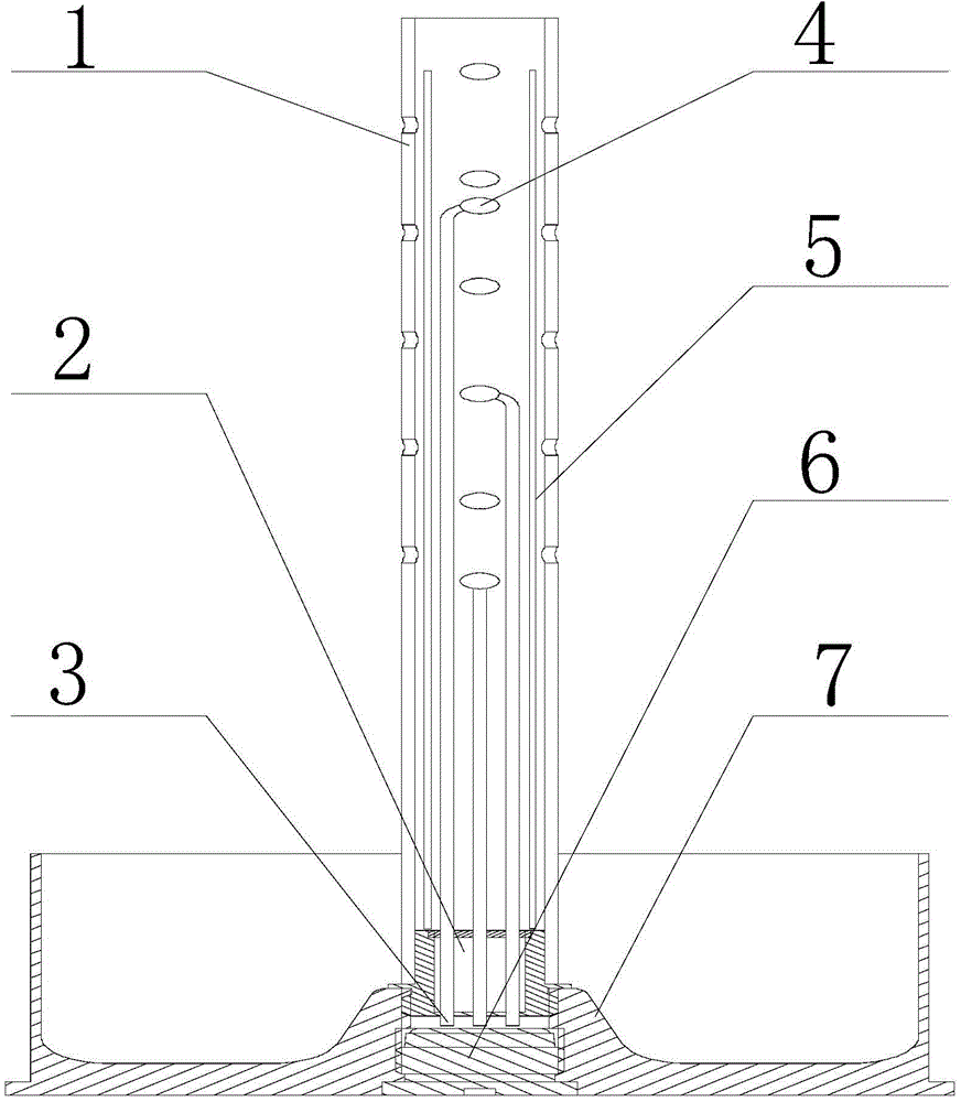
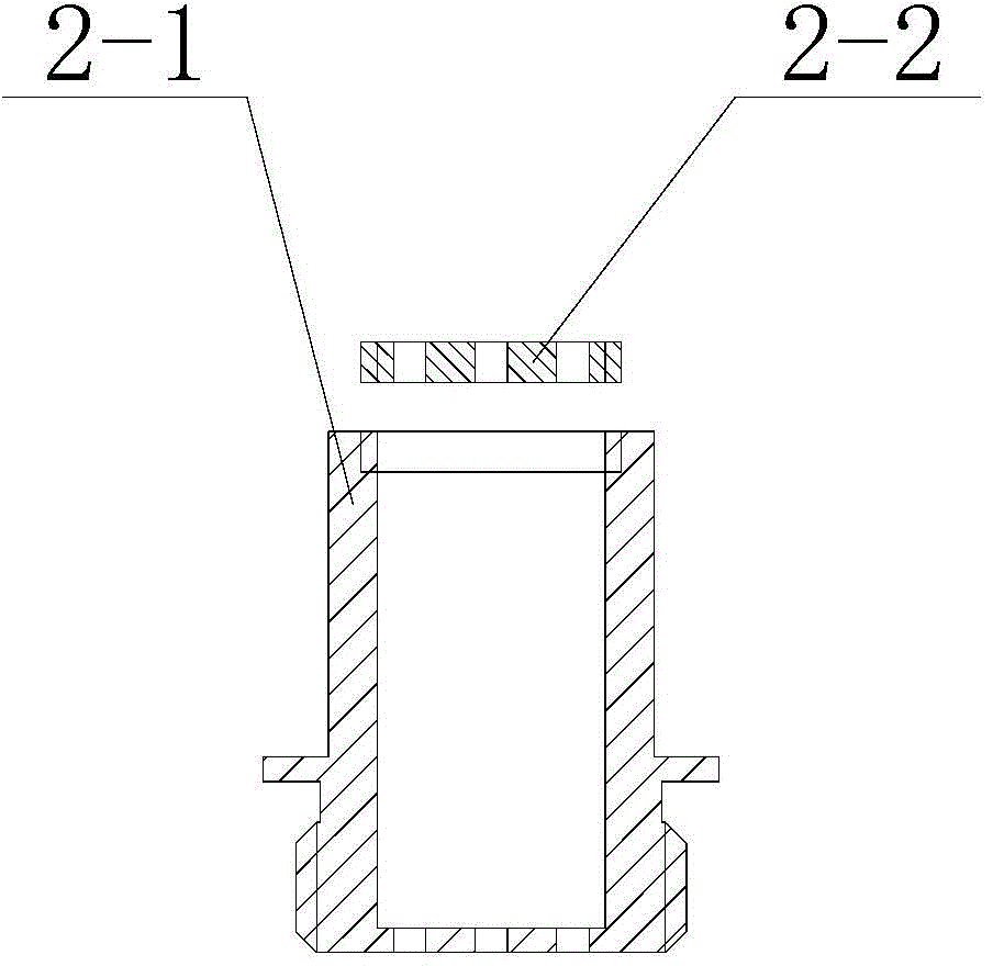
[0013] as figure 1 As shown, the synchronous multi-point ignition central fire transmission tube provided by the first preferred embodiment of the present invention includes a central fire transmission tube body 1, a fire transmission tube adapter 2, a nonel tube 3, an ignition charge package 4, and a naphthalene charge tube 5. Primer 6 and cartridge 7. The center fire tube body 1 is a steel fire tube with a length of 360mm, an inner diameter of 18mm, and an outer diameter of 24mm. The pipe wall of the main body is provided with equidistant and cross-arranged small circular holes. The height of the first hole is 160mm, the hole diameter is 3mm, the hole distance is 40mm, and there are 20 holes in 5 rows. The top of the central fire transmission tube body 1 and the round hole of the tube wall are sealed with a celluloid sheet with ...


PUM


Abstract

The invention discloses a synchronous multi-point ignition center core igniter and aims at solving the problem of bottom ignition defects in the prior art. The synchronous multi-point ignition center core igniter consists of a center core igniter, a core igniter adapter, multiple detonator tubes, multiple igniter packages, a benzene and naphthalene powder tube, primer and a cartridge case, wherein the primer output end of the cartridge case is connected with one end of each detonator tube; the other end of each detonator tube is connected with the igniter packages; the igniter packages are axially and uniformly distributed in an ignition tube; and the benzene and naphthalene powder tube serving as axial igniting primer is arranged in the center core igniter. Synchronous multi-point ignition is realized in the center core igniter, and the igniting primer in the core igniter is almost ignited simultaneously, so that the simultaneous flaming effect is achieved by virtue of each flaming hole of the core igniter, and the ignition simultaneity of the gun propellant charge is improved. Therefore, the ignition reproducibility is improved, and stable ballistic performance is obtained. In addition, compared with a center core igniter with bottom ignition, the synchronous multi-point ignition center core igniter has the advantages that pressure waves in a hearth can be effectively inhibited by virtue of rapid and disperse ignition, and the gun firing safety is improved.

Description

technical field [0001] The invention belongs to the technical field of propellants and explosives, and is suitable for an ignition system of artillery propellant charges. Background technique [0002] The ignition system in the propellant charge has a crucial influence on the performance of barrel weapons. The requirements for the ignition system are: firstly, it must have the energy necessary to ignite the charge in the powder chamber; secondly, the ignition of the charge should be uniform and dispersed; thirdly, the ignition should have good reproducibility. [0003] At present, there are two kinds of ignition systems that are practically used for artillery charges: ignition by pyrotechnics and ignition by the central fire tube. The ignition of the pyrotechnic product is due to the ignition at the bottom, and an initial pressure gradient will be formed at the bottom of the powder chamber. The gas of the ignition powder, hot solid particles and ignited propellant gas penet...

Claims


Application Information

Patent Timeline
IPC IPC(8): F42C19/00
Inventor 赵宝明赵宏立靳建伟刘来东张衡杨丽侠张邹邹王琼林魏学涛张玉成
Owner XIAN MODERN CHEM RES INST
Learn More