
Novel tip-heated soldering iron head

A soldering iron tip and hot tip technology, which is applied in the field of new tip hot soldering iron tips, to achieve the effect of shortening the heat conduction distance

Inactive Publication Date: 2015-04-22
周晅民
View PDF6 Cites 3 Cited by
  • Summary
  • Abstract
  • Description
  • Claims
  • Application Information

AI Technical Summary

Problems solved by technology

Thoroughly solve the problems of disasters and personal safety accidents caused by the use of existing electric soldering irons

Method used


Image

  • Novel tip-heated soldering iron head
  • Novel tip-heated soldering iron head
  • Novel tip-heated soldering iron head

Examples


specific Embodiment approach

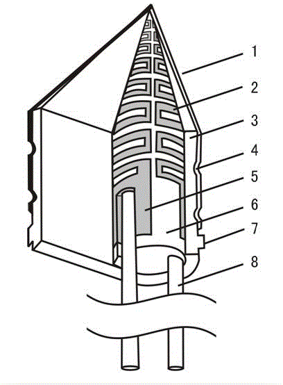
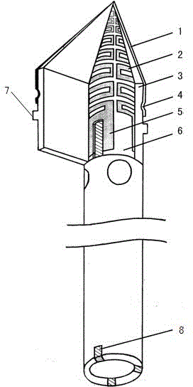
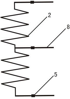
[0034] The technical solution adopted in the present invention is: this new type of pointed hot-type soldering iron head includes: heating element 3, ceramic core 6 preset in heating element 3, resistance 2, wiring area 5, conductive pin 8 and setting on heating element 3 Outer metal layer 1, concave ring 4, fixed ring 7. The heating element 3 of the present invention is mainly made of insulating ceramics, directly made into the shape of a soldering iron tip, and the material of the resistance 2 is preset in the front tip, and the concave ring 4 and the fixed ring 7 are arranged outside it, and the conductive pin 8 is arranged at the rear end. , formed by high-temperature sintering, and an outer metal layer 1 is set on the front tip.

[0035] In the above technical scheme, the production method uses a high-temperature co-sintering technology similar to Metal Ceramics Heater cermets. The material of the resistor 2 is a slurry containing metal tungsten, molybdenum, manganese...

Embodiment

[0042] see figure 1 , Figure 4 , single-conductive pin tip-hot soldering iron head, only one conductive metal pin 8 is provided at the rear end of the heating element 3 to connect with the resistor 2, and it is inserted into the supporting socket 10 of the main body of the electric soldering iron during installation, and the electrode at the other end of the resistor is led out of the heating body 3 is connected with the outer metal layer 1, and the outer metal layer 1 is connected with the shell of the soldering iron body through the metal protective sheath 9, and the circuit is connected. The circuit principle is the same as that of most existing flashlights. Pointed thermal tip with single conductive pin is only suitable for rechargeable soldering iron with safe power supply.

[0043] see figure 2 , image 3 , Figure 4 , the pointed hot-type soldering iron tip with three conductive pins, the pointed hot-type soldering iron tip with three conductive pins, in ...


PUM


Abstract

The invention relates to a novel tip-heated soldering iron head. The novel tip-heated soldering iron head comprises an outer metal layer, a heating body and conductive pins and is characterized in that the heating body takes ceramics as a main body and is directly made into a soldering iron head shape, a resistive material is pre-placed inside the front tip end of the heating body, the conductive pins are arranged at the rear end of the heating body and are formed through high-temperature sintering, and the outer metal layer is arranged outside the front tip end of the heating body. According to the novel tip-heated soldering iron head, energy-accumulated tip heating is adopted, the heat conduction distance is less than 1 / 40 that of the existing external heating type electric soldering irons, the preheating is extremely fast, and tin can be melted and be used for soldering in few seconds, so that the novel tip-heated soldering iron head is energy-efficient; the novel tip-heated soldering iron head further has an automatic-thermostatic characteristic, so that high-temperature oxidation iron burning is prevented, and the service life is long; a charging soldering iron produced from the tip-heated soldering iron head disclosed by the invention is simple in structure, flexible in operation, convenient in carrying and low in power and is powerful; an automatic reset switch is mounted on a handle of the electric soldering iron, and the electric soldering iron is powered off through unclasping hands, so that the problems of the existing electric soldering irons that personal safety accidents and fires are caused due to current leakage, iron-damaged power cords and plug unplugging forgetting are thoroughly solved.

Description

technical field [0001] The invention relates to a soldering tool, in particular to a novel sharp-hot soldering iron tip installed on an electric soldering iron and having a heating function. Background technique [0002] The electric soldering iron is not only an essential tool for many manufacturing industries, maintenance industries, and model aircraft and sea model enthusiasts, but it is also widely used in science and technology laboratories and electronic DIY classrooms in universities, middle schools, and primary schools across the country. With the rapid development of modern technology, electric The scope of application of soldering iron is also wider and wider, for example: the use is extended to the toy industry, advertising sign industry, etc., and has even become a must-have tool for many families, for example: for D I Y assembly of mobile phone charging treasure, etc., but using the existing electric soldering iron But there are serious security risks. Accordin...

Claims


Application Information

Patent Timeline
Patent Type & Authority Applications(China)
IPC IPC(8): B23K3/03
CPCB23K3/0392B23K3/0323
Inventor 周晅民
Owner 周晅民
Learn More