Embedded type security device based on two channels
An embedded, channel technology, applied in the direction of anti-theft alarms, instruments, alarms, etc., can solve the problems of high false alarm rate, inability to distinguish external signals, short monitoring distance, etc., to improve accuracy, facilitate concealed installation, Small size effect
- Summary
- Abstract
- Description
- Claims
- Application Information
AI Technical Summary
Problems solved by technology
Method used
Image
Examples
Embodiment 1
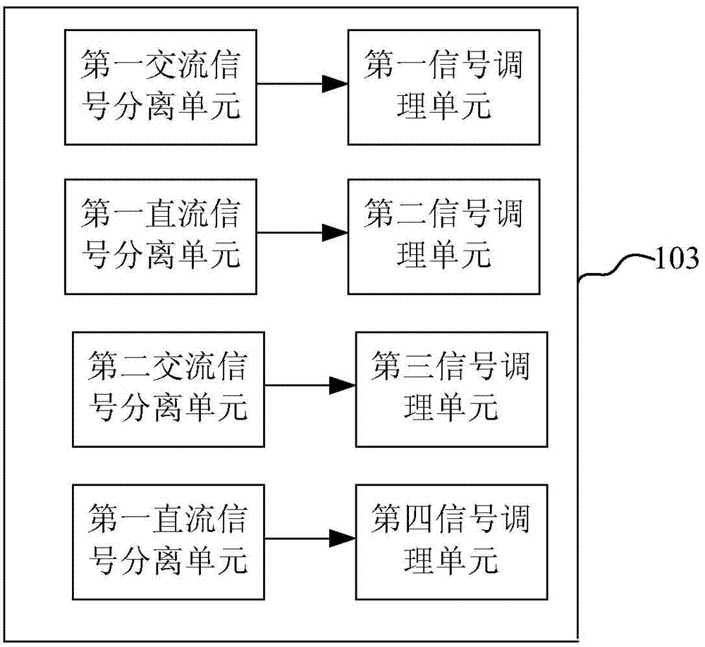
[0035] Embodiment 1 of the present invention provides a two-channel embedded security device. figure 2 It is a diagram of a two-channel embedded security device provided by Embodiment 1 of the present invention. Such as figure 2 As shown, the security device includes: a first photoelectric triode 101, a second photoelectric triode 102, an electrical signal processing module 103, a main controller 104, an optical control board 105, a light source 106, and a 1×2 coupler 108 , the first fiber optic flange 109 and the second fiber optic flange 110;
[0036] The output end of the first photoelectric triode 101 is connected to the first input end of the electrical signal processing module 103, for receiving the optical signal of the first channel in the optical cable, and converting the optical signal of the first channel is the first electrical signal; the output end of the second photoelectric triode 102 is connected to the second input end of the electrical signal processing ...
Embodiment 2
[0052] image 3 It is a schematic diagram of the optical path of a two-channel embedded security device provided by Embodiment 2 of the present invention, as shown in image 3 As shown, the optical path device includes a light source 1, a PIN photodiode 2, a fiber coupler 3, a delay ring 4, a Faraday rotating mirror 5, and an optical fiber connection line;
[0053] The light source 1 is the light source 106 provided by the first optical fiber flange 109 and the second optical fiber flange 110 of the two-channel embedded security device; The tube 101 is connected to the second photoelectric triode 102; the light source 1 and the PIN photodiode 2 are connected to the input end of the fiber coupler 3, the fiber coupler 3 is connected to the delay ring 4, and the output end of the fiber coupler 3 is connected to the vibration optical cable, and the vibration The end of the optical cable is connected with the Faraday rotating mirror 5 .
[0054] Analyze the optical path of the op...
PUM
 Abstract
Description
Claims
Application Information
 - R&D
- Intellectual Property
- Life Sciences
- Materials
- Tech Scout
- Unparalleled Data Quality
- Higher Quality Content
- 60% Fewer Hallucinations
Browse by: Latest US Patents, China's latest patents, Technical Efficacy Thesaurus, Application Domain, Technology Topic, Popular Technical Reports.
© 2025 PatSnap. All rights reserved.Legal|Privacy policy|Modern Slavery Act Transparency Statement|Sitemap|About US| Contact US: help@patsnap.com


