
Rear side grouting device for pile

A technology of grouting device and grouting pipe, which is applied in the direction of construction and basic structure engineering, etc., can solve the problems of increasing the corrosion rate of steel bars, the inability to implement the grouting process, and destroying the integrity of the pile body, so as to improve the pile side resistance, increase Pile-soil contact area, good operability effect

Active Publication Date: 2015-04-15
GUANGZHOU CHEM GROUTING CO LTD CAS
View PDF8 Cites 9 Cited by
  • Summary
  • Abstract
  • Description
  • Claims
  • Application Information

AI Technical Summary

Problems solved by technology

[0009] 1. The grouting port of the pre-buried pipe is blocked due to high pressure when pouring concrete, which makes the post-grouting process unable to be implemented;
[0010] 2. The post-grouting process must start before the initial setting of the concrete. The high-pressure breaks through the concrete at the hole to form a grouting channel, destroying the integrity of the pile body and increasing the corrosion rate of the steel bar;
[0011] 3. The grouting material is mainly cement grout, and there are also two-component polyurethane as the main material. The reinforcement effect is remarkable, but because the grout only penetrates along the weak parts of the soil, the reliability is low, resulting in large discrete pile bearing capacity.

Method used


Image

  • Rear side grouting device for pile
  • Rear side grouting device for pile
  • Rear side grouting device for pile

Examples


Embodiment Construction

[0034] The present invention will be further described below in combination with two specific embodiments.

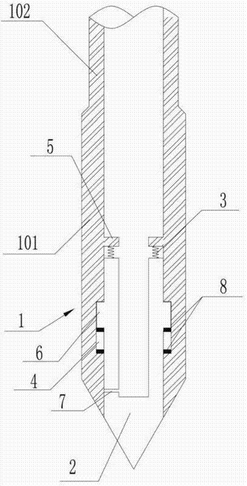
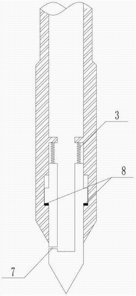
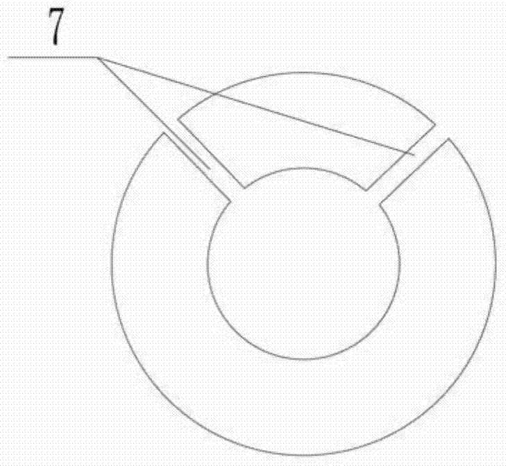
[0035] Such as Figure 1 to Figure 3 As shown, the post-pile grouting device described in this embodiment includes a grouting pipe 1, a grouting head 2 and a spring 3, wherein the outlet end of the grouting pipe 1 is a truncated cone, and its inner cavity The side wall is respectively provided with an annular clamping groove 4 and a retaining ring 5 extending along its circumference, and the annular retaining groove 4 is located between the retaining ring 5 and the outlet of the grouting pipe 1; the head of the grouting head 2 It is a cone, whose taper is consistent with the above-mentioned truncated cone, and can form a conical surface together with the truncated cone, and the cone angle is 60 degrees; the tail of the grouting head 2 extends from the outlet of the grouting pipe 1 into the grouting Inside the pipe 1, grouting holes 7 and snap rings 6 extending along it...


PUM


Abstract

The invention discloses a rear side grouting device for a pile, which comprises a grouting pipe, a grouting head and a spring, the outlet end of the grouting pipe is a truncated cone, the side wall of an inner cavity of the grouting pipe is provided with an annular clamping slot and a baffle ring, the head portion of the grouting head is a cone, the tail portion of the grouting head stretches into the grouting pipe from the outlet of the grouting pipe, the outer side wall of the grouting pipe is provided with a grouting hole and an edge clamping ring, the clamping ring is embedded into the annular clamping slot, one end of the spring abuts against the baffle ring, the other end of the spring abuts against the tail portion of the grouting head, the head portion of the grouting head is sealed, a hollow cavity is formed inside the grouting head, the hollow cavity is communicated with the grouting hole, and penetrates the tail portion of the grouting head; during grouting, a high polymer grouting material enters the cavity of the grouting head via the inner cavity of the grouting pipe under the action of high pressure, and is erupted via the grouting hole to form high-pressure jet flow. The rear side grouting device has stronger operability, wider applicability, more remarkable grouting effect, and higher reliability, does not need be pre-buried in a pile body, and does not generate any damage and influence on the original pile body.

Description

technical field [0001] The invention relates to the technical field of pile side post grouting, in particular to a pile side post grouting device. Background technique [0002] The bearing capacity of a pile is composed of two parts, including the pile side friction resistance and the pile end resistance. The theoretical calculation formula of the pile side resistance is shown in the following formula. [0003] R sk =u∑q si l i [0004] In the above formula ul i One item, that is, the circumference of the pile body section multiplied by the thickness of the soil layer is actually the pile-soil contact area, and the pile body section is usually circular. [0005] When the pile diameter and pile length are constant, the side resistance of the pile is related to the side friction resistance between the pile and soil. The greater the side friction resistance, the greater the pile side resistance, and the higher the pile bearing capacity. [0006] The so-called post groutin...

Claims


Application Information

Patent Timeline
Patent Type & Authority Applications(China)
IPC IPC(8): E02D15/02
CPCE02D15/04
Inventor 张文超薛炜古伟斌于方
Owner GUANGZHOU CHEM GROUTING CO LTD CAS
Learn More