
Low-temperature planetary high-energy bowl mill

A high-energy ball mill, planetary technology, applied in grain processing and other directions, can solve the problems of difficult operation of cooling pipes and cooling liquid circulation devices, unfavorable element alloying process, large volume of sealing devices, etc. The effect of increasing the contact area

Active Publication Date: 2015-04-08
GUANGXI UNIV
View PDF8 Cites 15 Cited by
  • Summary
  • Abstract
  • Description
  • Claims
  • Application Information

AI Technical Summary

Problems solved by technology

[0003] Traditional planetary high-energy ball mills generally work at room temperature. With the progress of the mechanical alloying process, the repeated impact of materials, balls and ball milling jars will cause the temperature of the entire ball milling jar and its interior to rise continuously. process is extremely unfavorable
The usual solution is to add airtight devices such as insulation covers and sealed boxes to the ball mill, and use low-temperature gas or liquid cooling fluid to maintain the low-temperature state during the mechanical alloying process. This method is simple to implement and achieves a certain cooling effect, but The volume of the sealing device is too large, which leads to a lot of waste of cooling materials, and brings a huge challenge to the long-term work of many mechanical parts at low temperature; another method is to wrap the cooling pipe around the ball mill tank, through the Circulating through the cooling liquid will take away the heat, thereby reducing the temperature of the ball mill tank. This method can be better realized in the vertical stirring ball mill, but it is difficult to install the cooling pipe and the cooling liquid circulation device in the planetary ball mill.

Method used


Image

  • Low-temperature planetary high-energy bowl mill
  • Low-temperature planetary high-energy bowl mill
  • Low-temperature planetary high-energy bowl mill

Examples


Embodiment Construction

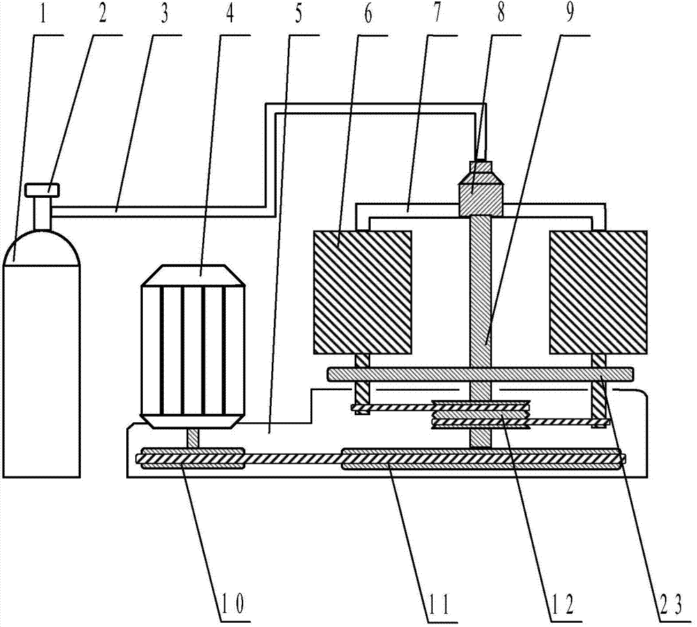
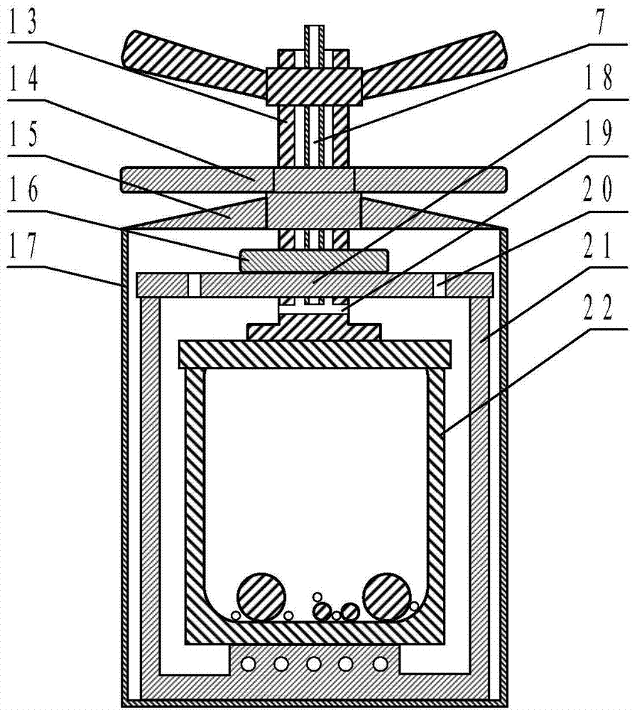
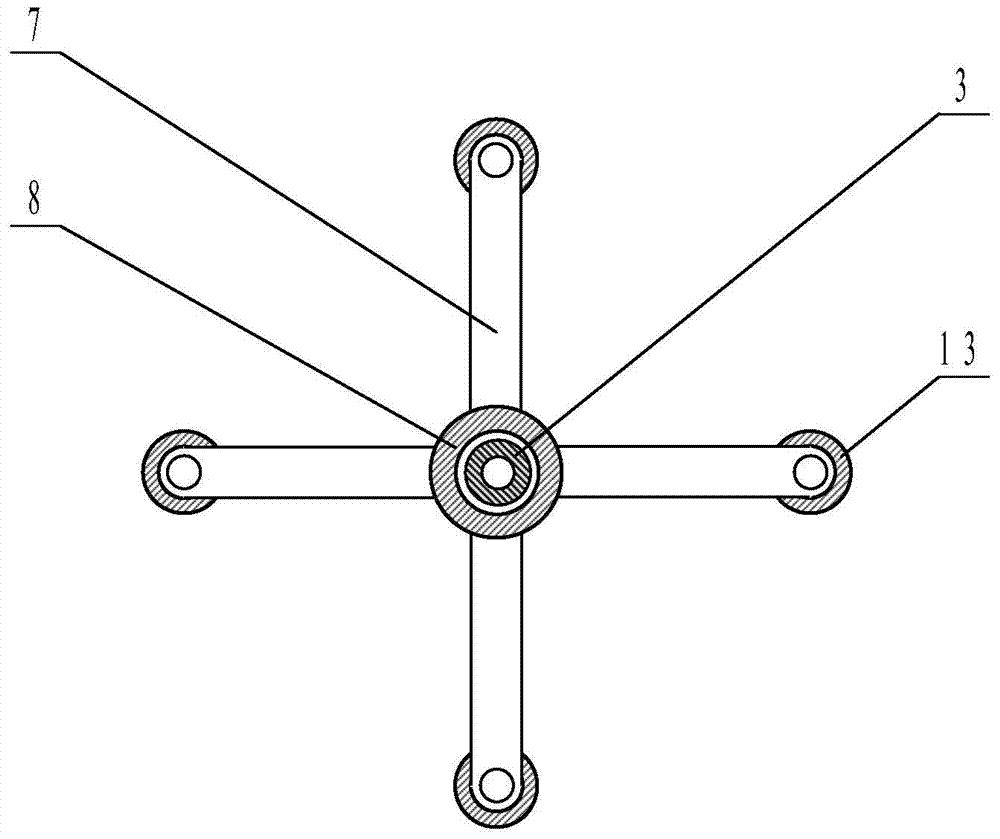
[0021] Such as figure 1 and figure 2 As shown, the low-temperature planetary high-energy ball mill of the present invention comprises four ball mill cylinders 6 and a base 5, and each ball mill cylinder 6 is composed of an insulated tank 21, a ball mill tank 22 and a toilet bowl 17, and the ball mill tank 22 is placed in the insulated tank 21 for heat preservation. The tank 21 is placed in the toilet 17, the inner wall of the insulation tank 21 has a heat-insulating coating, the material of the ball mill tank 22 and the balls is stainless steel or zirconia or alumina; the base 5 is equipped with a revolving main shaft 9 and a frequency conversion motor 4. The frequency conversion motor 4 drives the ball mill cylinder 6 to perform planetary motion through the transmission device. The coolant main input pipe 3 connected with the liquefied gas bottle 1 extends to the opening of the liquid storage tank on the upper part of the multi-port splitter head 8, and the other ports of t...


PUM


Abstract

A disclosed low-temperature planetary high-energy bowl mill comprises a pedestal and a ball mill cylinder; the pedestal is provided with a revolution main shaft and a variable-frequency motor; an outlet of a cooling-liquid total input pipe aims at a liquid storage tank at the top of a multi-port flow-dividing head, and other ports at the bottom of the multi-port flow-dividing head are respectively connected with flow-dividing input pipes; the ball mill cylinder is composed of thermal-insulation tanks, ball mill tanks and puller barrels, one ball mill tank is disposed in one thermal-insulation tank, and one thermal-insulation tank is disposed in one puller barrel; the top cover of each thermal-insulation tank is provided with a gas vent, a top cover press ring is arranged on the corresponding top cover; the top of each puller barrel is connected with a crossbeam; one flow-dividing input pipe is sleeved by a compaction screw rod, and the compaction screw rod successively penetrates one corresponding crossbeam, one corresponding top cover press ring and one corresponding top cover and enters one corresponding thermal-insulation tank, and the bottom of the compaction screw rod is provided with a flow discharge port; and the variable-frequency motor drives the ball mill tanks to make planetary motion through a transmission device. The low-temperature planetary high-energy bowl mill is extremely good in cooling effect, and is capable of precisely efficiently conveniently preparing relatively small and passivated nano-particles or amorphous alloy powders in a saving way.

Description

technical field [0001] The invention relates to the technical field of ball mills, in particular to a low-temperature planetary high-energy ball mill. Background technique [0002] Planetary high-energy ball mills can crush and grind materials, and are widely used in metallurgy, minerals, chemicals, medicine, geology and other fields. The planetary ball mill is equipped with four ball milling pots on the same main shaft turntable, and each ball milling pot also rotates around the main shaft and rotates at the same time, that is, planetary motion. Compared with other ball mills, it has higher impact force and impact frequency, and can better crush and weld powder. It is an important equipment for mechanical alloying in material preparation. The material preparation process belongs to powder alloying in non-equilibrium state. Using long-term high-energy impact and rolling between materials, grinding balls and ball milling tanks, the materials are repeatedly deformed, cold wel...

Claims


Application Information

Patent Timeline
IPC IPC(8): B02C17/08B02C17/18
CPCB02C17/08B02C17/10B02C17/1815
Inventor 欧阳义芳张雷陈红梅陶小马王戎丞莫小明
Owner GUANGXI UNIV
Learn More