
Air-assisted hydraulic air booster pump for magnetically levitated train

A technology of magnetic levitation trains and gas top fluid, which is applied to vehicle components, brakes, transportation and packaging, etc., can solve the problems of no guide device for the gas piston, unilateral wear and easy falling off of the gas piston apron, and improve reliability and Long service life, avoid shedding and wear, avoid the effect of unilateral wear

Inactive Publication Date: 2015-04-01
WUHU SHENGLI TECH SHARES
View PDF10 Cites 1 Cited by
  • Summary
  • Abstract
  • Description
  • Claims
  • Application Information

AI Technical Summary

Problems solved by technology

[0004] The air piston in the prior art has no guiding device, and long-term work causes unilateral wear of the air piston apron, which has a great impact on the durability of the afterburner pump
[0005] In addition, the Y-shaped ring on the connection cover in the prior art has no fixing device, and it is easy to fall off after a long time of work, which has a great impact on the durability of the afterburner pump.
[0006] like figure 1 As shown, the filter screen 30 in the respirator in the prior art adopts nylon gauze, therefore, in the case of bad working conditions, the respirator cannot completely block dust and foreign matter from entering the inside of the cylinder body through a long period of work, and the added The durability of the force pump is greatly affected

Method used


Image

  • Air-assisted hydraulic air booster pump for magnetically levitated train
  • Air-assisted hydraulic air booster pump for magnetically levitated train
  • Air-assisted hydraulic air booster pump for magnetically levitated train

Examples


Embodiment Construction

[0026] The specific implementation of the present invention will be described in further detail below by describing the embodiments with reference to the accompanying drawings, so as to help those skilled in the art have a more complete, accurate and in-depth understanding of the inventive concepts and technical solutions of the present invention.

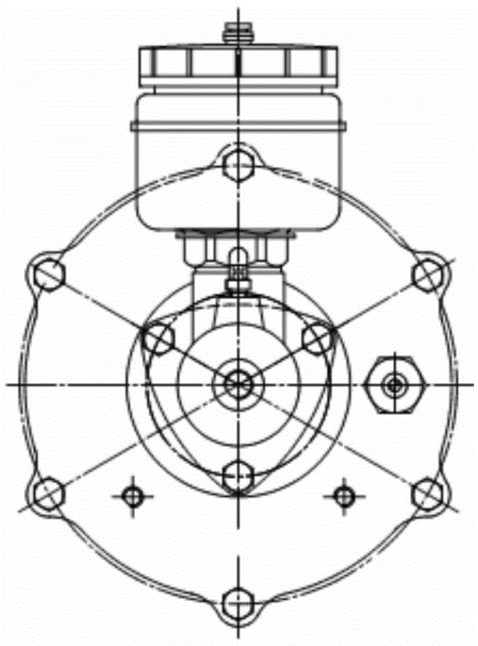
[0027] Such as Figure 5 , Figure 6 The structure of the present invention shown is a gas-top-liquid air booster pump for maglev trains, also known as CXF614 air booster pump. Connection relationship of the present invention: the air booster pump air inlet is connected with the air brake valve (an original valve in the system) air outlet, and the oil outlet is connected with the brake oil inlet.

[0028] The air booster pump includes a cylinder block assembly 1, an air piston 2, a hydraulic cylinder block 9, and a hydraulic piston assembly 11; the cylinder block assembly 1 and the hydraulic cylinder block 9 are tightly connected ...


PUM


Abstract

The invention discloses an air-assisted hydraulic air booster pump for a magnetically levitated train. An air cylinder body assembly and a hydraulic cylinder body are fastened and connected through a connecting cover, wherein a respirator assembly is arranged on the connecting cover, a pneumatic piston and a hydraulic piston assembly are connected through a push rod passing through an inner hole of the connecting cover, the push rod is connected with the hydraulic piston assembly through a push rod seat, a hydraulic piston sealing seat is arranged in the hydraulic piston assembly, and one side, facing the push rod seat, on the hydraulic piston sealing seat is provided with sealing rubber. The technical scheme is adopted, the direction of a rubber sealing surface is changed, the front side impact of high pressure oil on the sealing rubber is avoided, a guide ring is added to the pneumatic piston, and single-edge abrasion of a pneumatic piston rubber ring can be avoided, a support ring is added, the falling and abrasion of a Y-shaped ring can be avoided, and through the improvement on a respirator, the cleanness of an air cylinder assembly is ensured, so that the reliability of a product is improved, and the service life of the product is prolonged.

Description

technical field [0001] The invention belongs to the technical field of high-speed train braking devices. More specifically, the present invention relates to a gas cap liquid air booster pump for a maglev train. Background technique [0002] In the prior art, the push rod seat of the hydraulic chamber of the air booster pump is positively sealed. When the product returns to its position, the high-pressure oil in the pipeline impacts the rubber on the push rod seat and causes damage, resulting in seal failure and brake failure. . [0003] Such as image 3 and Figure 4 Shown: [0004] The gas piston in the prior art has no guide device, and long-time work causes unilateral wear of the gas piston apron, which has a great impact on the durability of the afterburner pump. [0005] In addition, the Y-shaped ring on the connecting cover in the prior art has no fixing device, and it is easy to fall off after a long time working, which greatly affects the durability of the afterb...

Claims


Application Information

Patent Timeline
IPC IPC(8): B60T13/10B60T13/138
CPCB60T13/16
Inventor 张武江左新珍孙海侠乔跃平胡丹红彭涛殷国柱叶新年王安芝王华张兆铭林苏一
Owner WUHU SHENGLI TECH SHARES
Learn More