
Bidirectional cutting edge polycrystalline diamond compact for high-frequency rotation vibration rock cutting

A technology of polycrystalline diamond and cutting edge, which is applied in the field of drilling and drilling, can solve the problems of low service life and unsatisfactory effect of polycrystalline diamond composite sheets, and achieve the effects of increased life, small vibration of surrounding rock, and avoiding one-sided wear

Active Publication Date: 2019-06-14
JILIN UNIV
View PDF9 Cites 0 Cited by
  • Summary
  • Abstract
  • Description
  • Claims
  • Application Information

AI Technical Summary

Problems solved by technology

Drilling to overcome this type of formation is often accomplished by using a diamond drill bit combined with hydraulic axial impact, torque impact, or hydraulic axial impact combined with torque impact, but the effect is still not ideal
In view of the above difficulties, a high-frequency rotary vibration rock breaking method and equipment are disclosed in the Chinese patent literature. See the application number 201811148280.5 for details, which fundamentally solves the problem of hard rock drilling. Only one-way cutting can be achieved, and the service life of the polycrystalline diamond composite sheet is low

Method used


Image

  • Bidirectional cutting edge polycrystalline diamond compact for high-frequency rotation vibration rock cutting
  • Bidirectional cutting edge polycrystalline diamond compact for high-frequency rotation vibration rock cutting
  • Bidirectional cutting edge polycrystalline diamond compact for high-frequency rotation vibration rock cutting

Examples


Embodiment Construction

[0015] In order to illustrate the present invention more clearly, the present invention will be further described below in conjunction with preferred embodiments and accompanying drawings. Those skilled in the art should understand that the content specifically described below is illustrative rather than restrictive, and should not limit the protection scope of the present invention. Unless otherwise defined, the technical terms or scientific terms used herein shall have the usual meanings understood by those skilled in the art to which the present invention belongs. In the description of the present invention, it should be understood that the terms "first" and "second" are used for descriptive purposes only, and the features limited to "first" and "second" do not indicate any order, quantity or importance nature, but only to distinguish different components.

[0016] The present invention provides a bidirectional cutting edge polycrystalline diamond composite sheet for high-...


PUM


Abstract

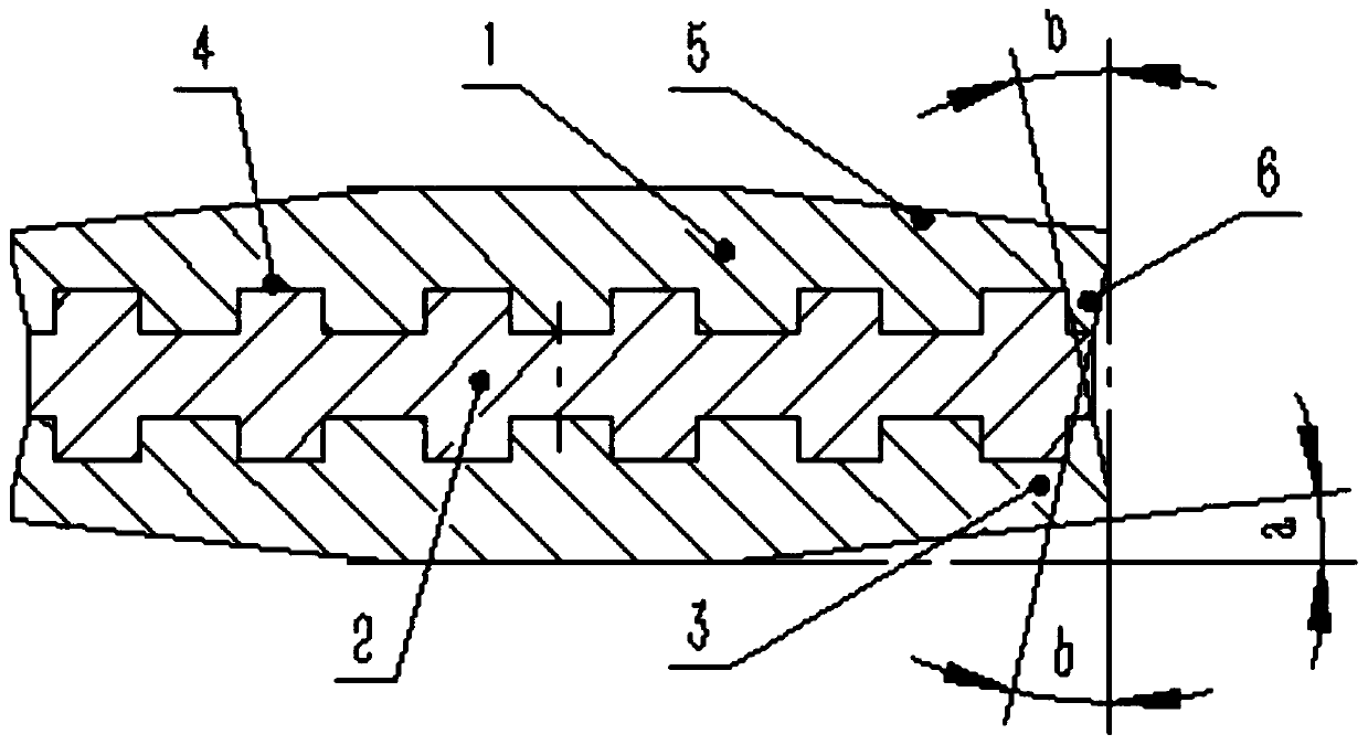
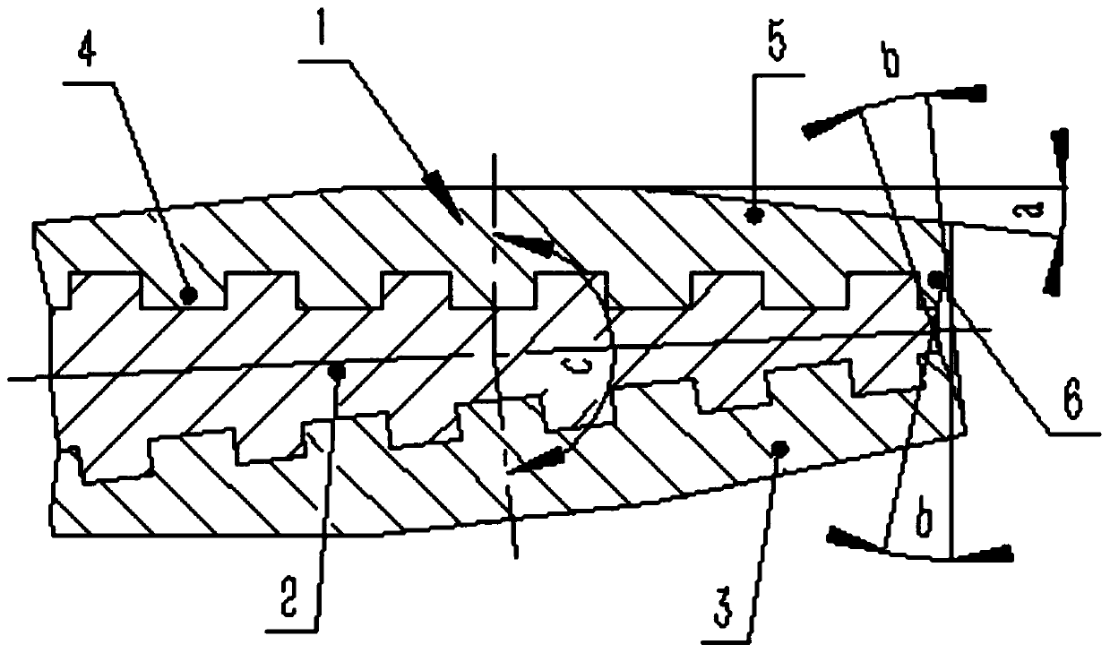
The invention discloses a bidirectional cutting edge polycrystalline diamond compact for high-frequency rotation vibration rock cutting, and belongs to the technical field of drilling exploration andwell drilling. The bidirectional cutting edge polycrystalline diamond compact consists of a first polycrystalline diamond layer, a hard alloy layer and a second polycrystalline diamond layer, whereinthe first polycrystalline diamond layer and the second polycrystalline diamond layer have the identical structures; the hard alloy layer is clamped and arranged between the first polycrystalline diamond layer and the second polycrystalline diamond layer; the two sides of the hard alloy layer are bonded with the first polycrystalline diamond layer and the second polycrystalline diamond layer in a high-temperature high-pressure sintering multi-surface combination mode; each of the first polycrystalline diamond layer and the second polycrystalline diamond layer is provided with a cutting surface,a cutting edge surface and a combination surface; the bidirectional cutting and hole forming is realized on a hard rock stratum with very weak grinding performance by the cutting edges of the first polycrystalline diamond layer and the second polycrystalline diamond layer under the condition of high-frequency rotation vibration; the vibration on surrounding rock is small; the single-side abrasionof the conventional single-cutting-edge polycrystalline diamond compact is avoided; and the service life of the polycrystalline diamond compact is prolonged.

Description

technical field [0001] The invention belongs to the technical field of drilling and well drilling, and relates to a high-frequency rotary vibration rock breaking tool, in particular to a bidirectional cutting edge polycrystalline diamond composite sheet for high frequency rotary vibration rock breaking. Background technique [0002] In drilling, the hard rock formation with extremely weak abrasiveness is characterized by dense and complete rock, high compression resistance hardness, and weak abrasiveness. Generally, the drilling time of diamond drill bits is extremely low, and the lip surface of the drill bit and the rock are polished each other. "Slip" phenomenon. As the drilling depth increases, the depth, frequency and thickness of similar hard and slippery formations increase, and drilling becomes extremely difficult. Drilling to overcome this type of formation is usually accomplished by using a diamond drill bit combined with hydraulic axial impact, torque impact, or h...

Claims


Application Information

Patent Timeline
IPC IPC(8): E21B10/46E21B10/54
Inventor 高科李潇侗谢晓波陈顺达牛鑫刘义坤
Owner JILIN UNIV
Learn More