
Control method of gas turbine power generation device used for energy storage of natural gas power station super capacitor and gas turbine power generation device

A technology of supercapacitor and gas turbine, which is applied in the direction of gas turbine device, motor generator control, electronic commutation motor control, etc., and can solve problems such as unstable operation of the system

Inactive Publication Date: 2015-03-25
HARBIN INST OF TECH
View PDF2 Cites 11 Cited by
  • Summary
  • Abstract
  • Description
  • Claims
  • Application Information

AI Technical Summary

Problems solved by technology

[0006] The purpose of the present invention is to enhance the anti-shock load capacity of the micro gas turbine power generation device used in natural gas power plants, improve the response speed of the device and the problem of unstable system operation caused by power conversion, and propose a gas turbine for super capacitor energy storage in natural gas power plants Control method of power generation device and gas turbine power generation device

Method used


Image

  • Control method of gas turbine power generation device used for energy storage of natural gas power station super capacitor and gas turbine power generation device
  • Control method of gas turbine power generation device used for energy storage of natural gas power station super capacitor and gas turbine power generation device
  • Control method of gas turbine power generation device used for energy storage of natural gas power station super capacitor and gas turbine power generation device

Examples


specific Embodiment approach 1

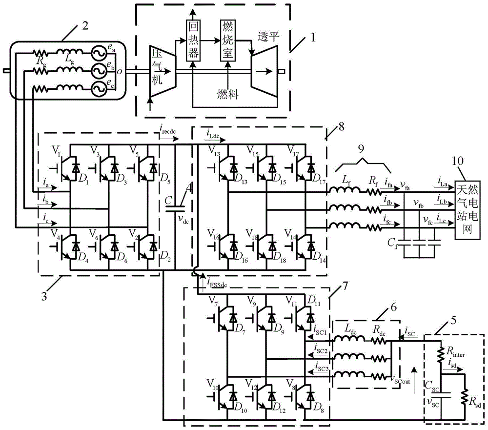
[0065] Specific implementation mode 1, refer to image 3 and Figure 4 This embodiment is specifically described. The control method of the gas turbine power generation device used for supercapacitor energy storage in natural gas power plants described in this embodiment is realized based on the gas turbine power generation device. The gas turbine power generation device includes a micro gas turbine 1, a permanent magnet synchronous Generator 2, PWM rectification switch module 3, DC filter capacitor 4, super capacitor 5, DC conversion switch module 7, inverter switch module 8 and natural gas power station grid 10;

[0066] The micro gas turbine 1 is coaxially connected with the permanent magnet synchronous generator 2, the stator three-phase line of the permanent magnet synchronous generator 2 is connected with the three-phase line of the AC side of the PWM rectifier switch module 3, and the bus bar of the DC side of the PWM rectifier switch module 3 A DC filter capacitor 4 i...

specific Embodiment approach 2

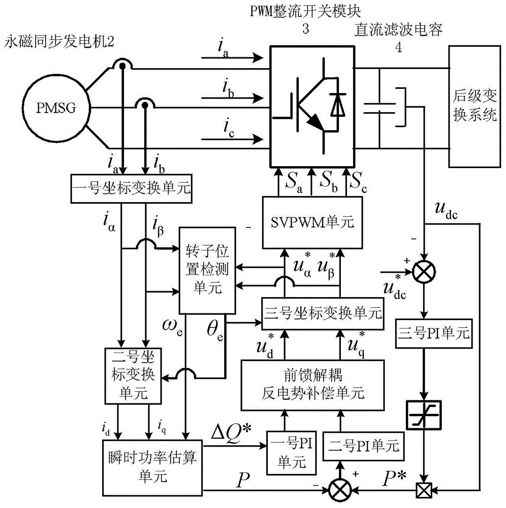
[0078] Specific implementation mode two, refer to image 3 Describe this embodiment. This embodiment is a further description of the control method of the gas turbine power generation device used for supercapacitor energy storage in natural gas power plants described in Embodiment 1. In this embodiment, the PWM rectification described in the start control method The switch module 3 converts the DC bus voltage into an AC bus voltage to drive the permanent magnet synchronous generator 2 to rotate and speed up, and the method for the PWM rectification switch module 3 to drive the permanent magnet synchronous generator 2 to rotate is as follows:

[0079] Stator current i a i b The stator current i in the two-phase static coordinate system is obtained after the No. 1 coordinate transformation unit α i β And output to the No. 2 coordinate transformation unit; output the stator current i under the two-phase synchronous rotating coordinate system after passing through the No. 2 coo...

specific Embodiment approach 3

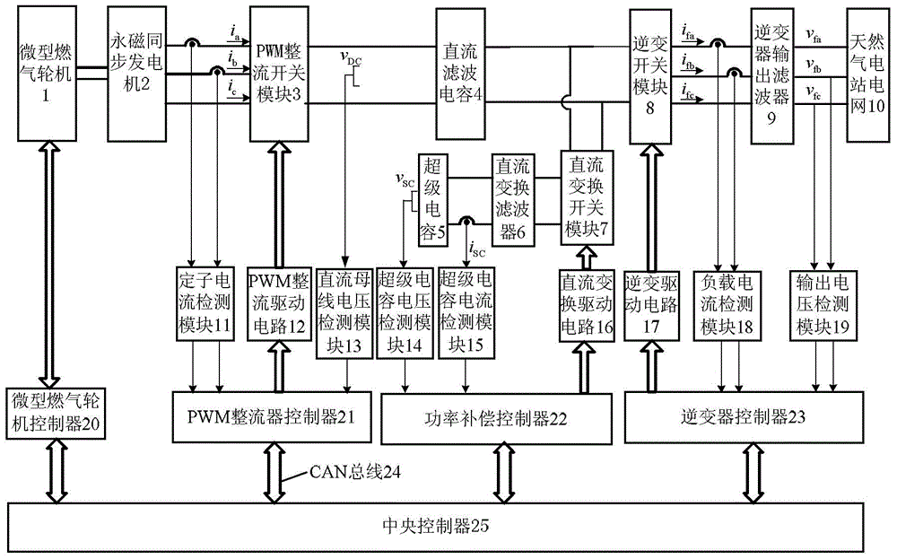
[0089] Specific implementation mode three, refer to figure 1 and figure 2 Describe this embodiment in detail, the gas turbine power generation device used for supercapacitor energy storage in natural gas power plants described in this embodiment includes power generation components and control power generation components; the power generation components include micro gas turbines 1, permanent magnet synchronous generators 2, PWM rectifiers Switch module 3, DC filter capacitor 4, super capacitor 5, DC conversion switch module 7, inverter switch module 8, inverter output filter 9 and natural gas power station grid 10; control power generation components include stator current detection module 11, PWM rectifier Drive circuit 12, DC bus voltage detection module 13, super capacitor voltage detection module 14, super capacitor current detection module 15, DC conversion drive circuit 16, inverter drive circuit 17, load current detection module 18, output voltage detection module 19,...


PUM


Abstract

The invention discloses a control method of a gas turbine power generation device used for energy storage of a natural gas power station super capacitor and the gas turbine power generation device and relates to the technical field of distributed power generation of micro gas turbines in order to enhance the anti-impacting-load capacity of the micro gas turbine power generation device used for a natural gas power station. A PWM rectification controller obtains a PWM driving signal after a stator current and a direct-current bus voltage are calculated so that a PWM rectification switch module can be driven; a power compensation controller obtains a direct-current conversion driving signal after a super-capacitor current and a super-capacitor voltage are calculated so that a direct-current conversion driving circuit can be driven; an inverter controller obtains an inversion driving signal after a load current and an output voltage are calculated so that an inversion switch module can be driven; a central controller controls the PWM rectification controller, the power compensation controller and the inverter controller to act and is further used for controlling a micro gas turbine through the backward signals of the PWM rectification controller, the power compensation controller and the inverter controller. The control method of the gas turbine power generation device used for energy storage of the natural gas power station super capacitor and the gas turbine power generation device are applicable to the fields where impacting loads exist and the natural gas power station needs to supply power.

Description

technical field [0001] The invention relates to the technical field of micro gas turbine distributed power generation, in particular to a control method for a gas turbine power generation device used for supercapacitor energy storage in a natural gas power station, a gas turbine power generation device for supercapacitor energy storage in a natural gas power station, and a control method based on the device . Background technique [0002] Micro gas turbines have the characteristics of high power density, high reliability, high efficiency, low maintenance, and low emissions. They can use a variety of fuels, such as natural gas, oilfield associated gas, diesel, etc., and can get rid of a single fuel form. It has broad application prospects in aerospace, national defense and other industrial fields such as ships and oil and gas exploration. In the development of distributed power systems characterized by diversification of energy sources, miniaturization of devices, cogenerati...

Claims


Application Information

Patent Timeline
Patent Type & Authority Applications(China)
IPC IPC(8): H02J3/38H02J3/28F02C9/00H02P21/00H02P101/25H02P103/20
CPCF02C9/00H02J3/28H02J3/381H02P21/00
Inventor 段建东李树生孙力王志刚国海峰王令金李寻迹郭安东张润松刘龙海赵克吴凤江安群涛
Owner HARBIN INST OF TECH
Learn More