
Bendable LED aluminum substrate light source and manufacturing method thereof

A technology of LED aluminum substrate and manufacturing method, which is applied in the field of LED light sources, and can solve problems such as heavy workload, many solder joints, and difficulty in ensuring soldering quality

Active Publication Date: 2015-03-25
广州阿尔卡诺科技有限公司
View PDF3 Cites 7 Cited by
  • Summary
  • Abstract
  • Description
  • Claims
  • Application Information

AI Technical Summary

Problems solved by technology

If you want to make a LED lamp in the shape of a fully luminous cylinder surrounded by 20 pieces, there is currently only one way to connect the 20 pieces of aluminum substrates, which is manual wiring, that is, using manual soldering. The aluminum substrates are connected to each other, and each aluminum substrate has at least two solder joints. When twenty aluminum substrates are combined, there are many solder joints, the workload is heavy, and the welding quality is difficult to ensure. Although there are many LED energy-saving lamps with high wattage bulbs, they emit light at 180 degrees after all, which cannot be compared with traditional energy-saving lamps.

Method used


Image

  • Bendable LED aluminum substrate light source and manufacturing method thereof
  • Bendable LED aluminum substrate light source and manufacturing method thereof
  • Bendable LED aluminum substrate light source and manufacturing method thereof

Examples


Embodiment Construction

[0024] specific implementation plan

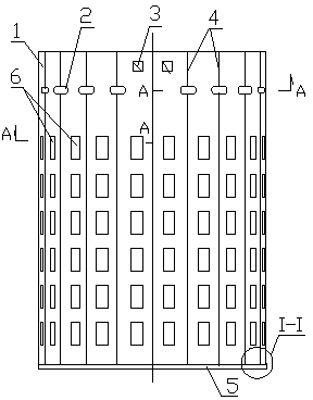
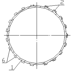
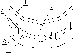
[0025] Such as Figure 1-Figure 9 As shown, the following is an embodiment of LED 360-degree light-emitting energy-saving lamps:

[0026] The bendable LED aluminum substrate light source includes an aluminum substrate 1 that is cylindrical after bending or a three-dimensional shape that needs to be bent (such as an approximate cylindrical shape, a prism) and a lamp bead 6 arranged on the aluminum substrate. According to the number of sides of the cylindrical aluminum substrate, before the aluminum substrate is bent, between the same long strips that make up the cylinder, along the mutual bending axis of every two long strips of the aluminum substrate, set a V cut on the aluminum alloy surface of the aluminum substrate. Line 4, a circuit board 8 is provided on the copper-clad surface of the aluminum substrate through the PCB manufacturing process, and a crossing pad 7 is provided through the PCB manufacturing process at the corresponding p...


PUM


Abstract

The invention discloses a bendable LED aluminum substrate light source and a manufacturing method of the bendable LED aluminum substrate light source. The bendable LED aluminum substrate light source comprises an aluminum substrate (1) and lamp beads (6) arranged on the aluminum substrate, wherein the aluminum substrate is bent to be a polygonal cylinder, V-shaped cutting lines (4) are arranged on an aluminum alloy surface needing to be bent oppositely according to identical faces constituting the polygonal cylinder before the aluminum substrate is bent, a circuit board (8) is arranged on the surface, coated with copper, of the aluminum substrate according to the PCB manufacturing technology, crossing bonding pads (7) are arranged at the positions where the circuit board correspondingly intersects with the V-shaped cutting lines according to the PCB manufacturing technology, soldering tin is welded to the crossing bonding pads through reflow soldering, after the lamp beads are attached to lamp bead bonding pads, the aluminum substrate is rolled to be cylindrical with the lamp beads on the outside, and female-male line plugs (3) are arranged at the positions of the V-shaped cutting lines of the aluminum substrates through welding. The invention provides an aluminum substrate manufacturing technology according to which an aluminum substrate can be bent without damaging or breaking a circuit. By the adoption of the technology, multi-faced LED lamps such as a multi-piece cylindrical LED lamp can be manufactured without manual line connection, and production efficiency is greatly improved.

Description

technical field [0001] The invention relates to an LED lamp, in particular to an LED light source which does not damage the circuit when the aluminum substrate is bent. Background technique [0002] Although the luminous efficiency of LED lamps is very high, the lamp beads commonly used in the market have a luminous efficiency of 100 to 120 lumens per watt, but dozens of percent of the electric energy is converted into heat energy, which must be dissipated into the air , otherwise, the temperature of the lamp bead will continue to rise. If the temperature is too high, it will affect the normal light emission of the lamp bead. Therefore, the lamp bead must be welded on a plate with good heat dissipation. At present, the most commonly used heat dissipation material is aluminum substrate, and ceramics are also used. For substrates, glass fiber boards are also used in places where the heat dissipation requirements are not high, but there is only one purpose, which is to export t...

Claims


Application Information

Patent Timeline
IPC IPC(8): F21S2/00F21V19/00H05K1/18H05K3/00F21Y101/02
CPCF21K9/20F21V19/001F21Y2101/00H05K1/182H05K3/043H05K3/34
Inventor 邓放明
Owner 广州阿尔卡诺科技有限公司
Learn More