Al technical title is built by PatSnap Al team. It summarizes the technical point description of the patent document.
A heavy oil catalysis and catalytic cracking technology, used in catalytic cracking, cracking, petroleum industry and other directions, can solve the problems of shortening the oil and gas residence time, affecting the yield of light oil, and long residence time, so as to improve product quality and improve catalyst activity. , the effect of improving coke yield
Inactive Publication Date: 2015-02-11
刘英聚
View PDF0 Cites 0 Cited by
Summary
Abstract
Description
Claims
Application Information
AI Technical Summary
This helps you quickly interpret patents by identifying the three key elements:
Problems solved by technology
Method used
Benefits of technology
Problems solved by technology
In some installations, 1 to 4 primary cyclone separators (coarse cyclone for short) are installed at the outlet of the riser, and the efficiency can reach more than 95%. The coarse cyclone leg discharges the catalyst under the condition of positive pressure difference, and discharges 15% to 30% of oil and gas at the same time. , this part of the oil and gas slowly rises from the lower part of the settler to the upper part, and the residence time is 30-90 seconds. At 500 °C, there are obvious transitional thermal cracking and condensation reactions, which affect the yield of light oil. When processing heavy oil, even Coking in the settler
Some devices extend the rough-rotating air pipe upwards to the vicinity of the top-rotating inlet. This scheme greatly shortens the residence time of the oil and gas mainstream, but the small amount of oil and gas discharged from the coarse-rotating material stays in the settler for a longer time (up to 100 seconds). There is a tendency for more serious coking
Method used
Image
Click on the blue label to locate the original text in one second.
Reading with bidirectional positioning of images and text.
Examples
Embodiment Construction
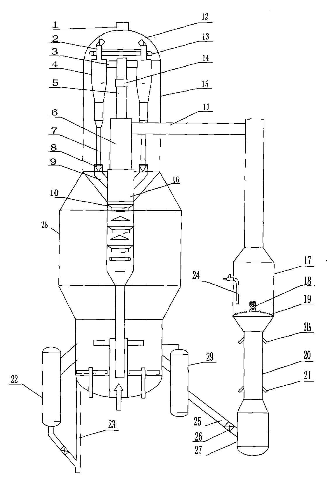
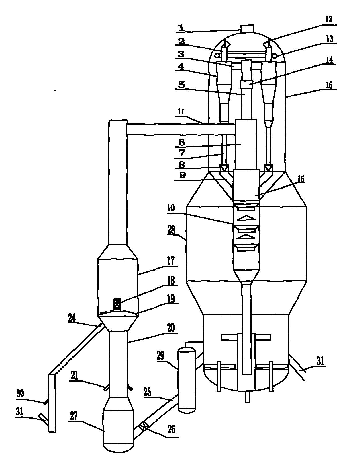
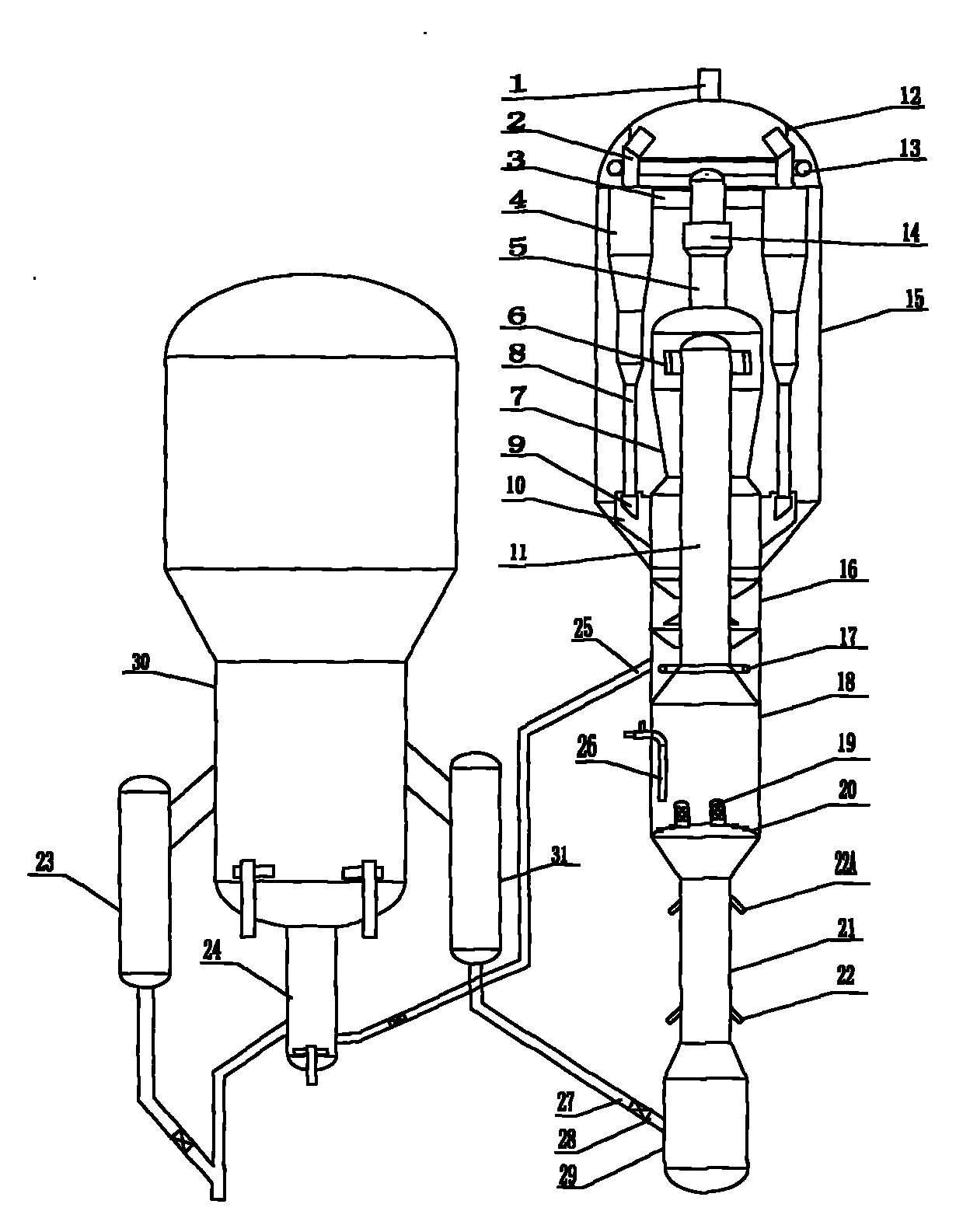
[0026] See figure 1 , figure 2, is applied to the coaxial device, the riser 11 horizontally enters the inside of the settler 15 and is connected with the cyclone 6; the upper part of the cyclone 6 is connected with the top cyclone 4 through the cyclone exhaust pipe 5, the top cyclone inlet pipe 3, and the cyclone 6 The lower end is connected to the stripping section 10 through the connecting cylinder 16; the upper end of the top rotation 4 is connected to the gas collection chamber 12 through the top rotation exhaust pipe 2, and the lower end is connected to the material leg 7 and the wing valve 8; the lower end of the catalyst guide pipe 9 is connected to the connecting cylinder 16 The lower part is connected, and the upper end wraps the wing valve 8. The middle heating section 17 is provided with a vertical distributor 18 and a plate distributor 19, the lower end of which is connected to the lower riser 20; The upper end of the low-temperature catalyst delivery pipe 25 is...
PUM
Abstract
The invention discloses a heavy oil catalytic cracking method, belongs to the technical field of petroleum chemical industry, is used for processing heavy oil, can improve the catalyst-to-oil ratio, reduces coke and dry gas yields, improves product yield, and solves reactor coking. The heavy oil catalytic cracking method includes the processes of catalyst feeding, raw material oil feeding, raw material oil vaporization, gas-solid contact, catalytic cracking reaction and gas-solid separation, and is characterized in that through arrangement of temperature reduction with a regeneration agent, heat collection with a pre-lifting device, and heat collection at the middle part of a lifting pipe reactor, the catalyst-to-oil ratio is increased, a mixing temperature of a feeding section is improved, the catalyst activity in the catalytic cracking process is improved, and the feeding heavy oil vaporization rate is improved; through arrangement of a closed fast separation system, the oil and gas residence time in a settler is shortened. The method can reduce the dry gas and coke yields, increase the product yield, improve the product quality and solve the problem of coking of the lifting pipe reactor and the settler. A device for realizing the method is also provided, includes a regeneration agent temperature reducer, the pre-lifting device, a heat collector, a lifting pipe middle-part heat collection facility and a closed fast separation facility, and is the catalytic cracking and catalytic pyrolysis device applied for processing the heavy oil.
Description
technical field [0001] The invention belongs to the technical field of petrochemical industry, in particular to a heavy oil catalytic cracking method and device. Background technique [0002] The catalytic cracking process is a process in which heavy oil undergoes a gas-solid catalytic cracking reaction on a catalyst to generate light oil. In the catalytic cracking industrial device, the liquid heavy feed oil enters the bottom of the riser reactor after being atomized, and the heavy feed oil is vaporized first when it contacts with the high-temperature regenerant, and then the gas-solid catalytic cracking reaction occurs, and the reaction product is oil gas and unborn catalyst It flows out from the outlet of the riser reactor, and the reaction product oil gas is discharged out of the reactor after gas-solid separation, and the raw catalyst is regenerated. Since catalytic cracking is an endothermic reaction and coke is generated, the temperature and catalyst activity in the ...
Claims
Application Information
Patent Timeline
Application Date:The date an application was filed.
Publication Date:The date a patent or application was officially published.
First Publication Date:The earliest publication date of a patent with the same application number.
Issue Date:Publication date of the patent grant document.
PCT Entry Date:The Entry date of PCT National Phase.
Estimated Expiry Date:The statutory expiry date of a patent right according to the Patent Law, and it is the longest term of protection that the patent right can achieve without the termination of the patent right due to other reasons(Term extension factor has been taken into account ).
Invalid Date:Actual expiry date is based on effective date or publication date of legal transaction data of invalid patent.