
Spacing layer double-exposure etching method

A double exposure and etching process technology, applied in electrical components, semiconductor/solid-state device manufacturing, circuits, etc., can solve the problems affecting the edge roughness of the etched structure line, affecting the quality of the etched edge, distortion, etc., to avoid etching The effect of uneven etching rate, improved line edge roughness, and improved etching quality

Active Publication Date: 2015-01-21
ADVANCED MICRO FAB EQUIP INC CHINA
View PDF4 Cites 2 Cited by
  • Summary
  • Abstract
  • Description
  • Claims
  • Application Information

AI Technical Summary

Problems solved by technology

At the same time, the uneven etching rate will also cause different etching areas to have different over-etching rates when the etching is completed, thus affecting the quality of the etched edge.
[0014] In addition, if Figure 5 As shown, the stress between the spacer layer 106 and the organic material 103 will cause the distortion of the line edge of the region 110 to be etched on the semiconductor substrate 101, thus affecting the line edge roughness of the etched structure

Method used


Image

  • Spacing layer double-exposure etching method
  • Spacing layer double-exposure etching method
  • Spacing layer double-exposure etching method

Examples


Embodiment Construction

[0050] In order to make the purpose, technical solution and advantages of the present invention clearer, the following will further describe the implementation of the present invention in detail in conjunction with the accompanying drawings.

[0051] Those skilled in the art can easily understand other advantages and effects of the present invention from the contents disclosed in this specification. The present invention can also be implemented or applied through other different specific implementation modes, and various modifications or changes can be made to the details in this specification based on different viewpoints and applications without departing from the spirit of the present invention.

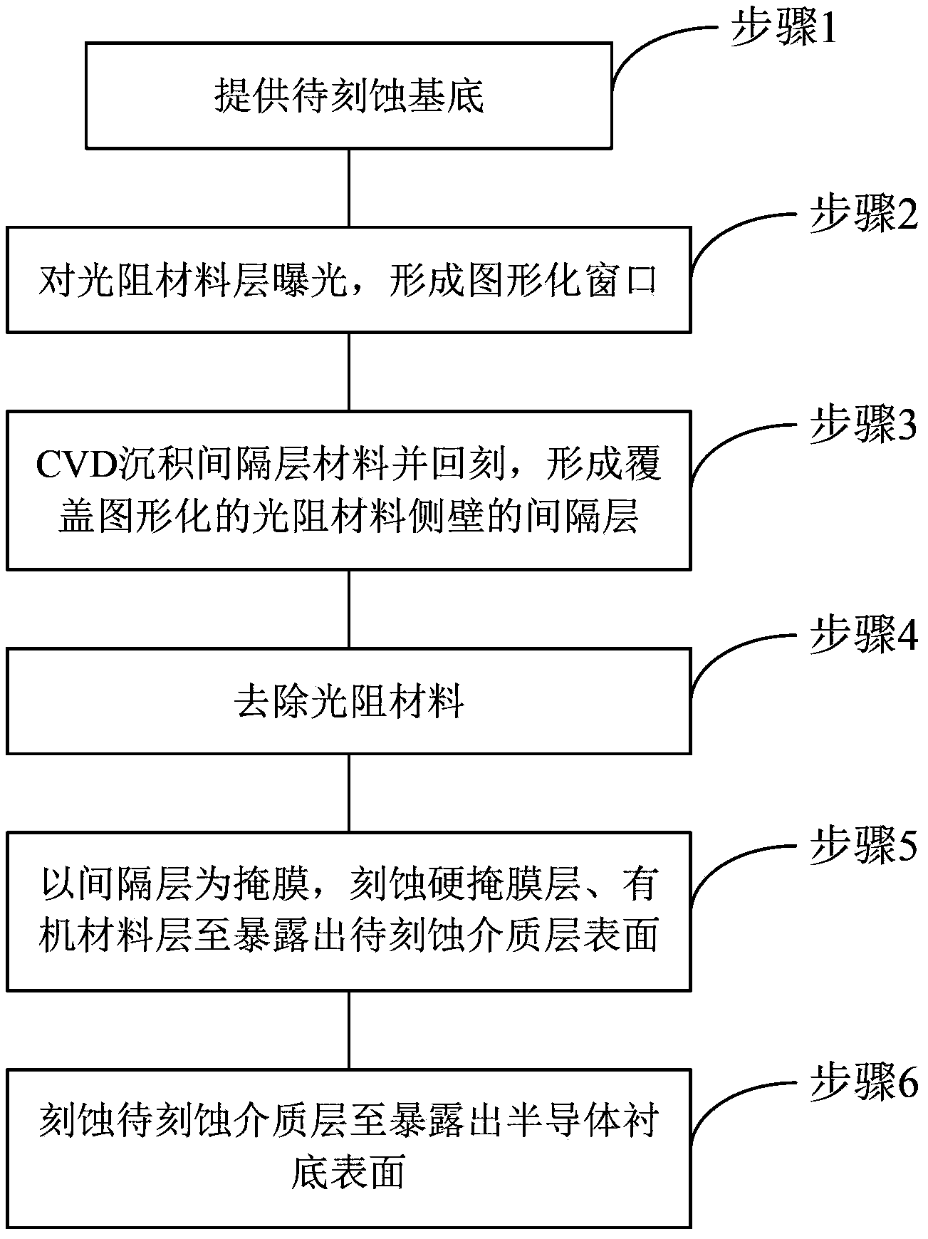
[0052] Figure 6 It is a flow chart of the steps of the double exposure etching method for the spacer layer provided by the present invention.

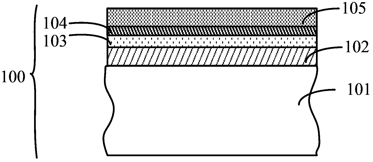
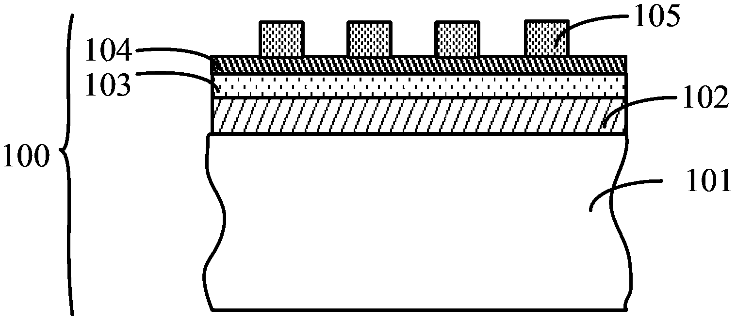
[0053] Such as Figure 6 As shown, the spacer layer double-exposure etching method provided in this specific embodiment includes the f...


PUM


Abstract

The invention relates to the technical field of semiconductors, and discloses a spacing layer double-exposure etching method. Before etching of an organic material layer and a semiconductor substrate, etching is performed on a spacing layer by adopting etching gas which contains CF4, Ar and Xe and is easy to form positive ion gas so that correction of the shape of the spacing layer is realized. Thickness of the spacing layer is reduced, and the shape of the spacing layer is corrected into a symmetrical or approximately symmetrical structure so that problems of uneven etching rate and over-etching caused by the spacing layer can be avoided. Meanwhile, the spacing layer is thinned via etching so that stress between the spacing layer and the organic material layer is reduced to some extent, and thus line edge roughness of the etching structure is improved and etching quality of the semiconductor substrate is enhanced.

Description

technical field [0001] The invention relates to the technical field of semiconductors, in particular to a spacer layer double exposure technology. Background technique [0002] With the continuous development of integrated circuit technology, semiconductor process nodes have gradually entered the era of 65nm and 45nm, and are moving towards more advanced 22nm and 16nm. However, as semiconductor process nodes continue to advance, the requirements for critical dimension (CD) in semiconductor device fabrication front-end process (FEOL) and back-end process (BEOL) become more and more stringent. Among them, the feature size of devices in the 65nm process has begun to be much smaller than the size of mainstream lithography. In the process of semiconductor device preparation, more and more semiconductor structures with feature sizes smaller than 65nm, or even smaller than 45nm and 32nm have begun to appear, and lithography has begun to become The bottleneck of the development of ...

Claims


Application Information

Patent Timeline
Patent Type & Authority Applications(China)
IPC IPC(8): H01L21/311
CPCH01L21/311H01L21/31116
Inventor 王兆祥杜若昕
Owner ADVANCED MICRO FAB EQUIP INC CHINA
Learn More