
Method for adjusting multi-magnetic-pole motion control

A control method and multi-pole technology, applied in the direction of discharge tubes, electrical components, circuits, etc., to achieve the effects of facilitating production and installation, realizing modularization, and simple circuits

Inactive Publication Date: 2015-01-21
BEIJING ZHONGKEXIN ELECTRONICS EQUIP
View PDF0 Cites 0 Cited by
  • Summary
  • Abstract
  • Description
  • Claims
  • Application Information

AI Technical Summary

Problems solved by technology

[0002] With the continuous advancement of modern CMOS technology, the types of ion implantation processes are increasing, and with the reduction of characteristic line width and the increase of process complexity, the traditional medium beam implanter can no longer meet the requirements of this process. Therefore, The challenges faced by the ion implantation process are reflected in the development of the implantation energy to the ultra-low end, while the implantation dose is developed to the high concentration. To solve this manufacturing process, it is necessary to develop a new ion implanter equipment—a low-energy and large-beam ion implanter. Solving the Shallow Junction Implant Process

Method used


Image

  • Method for adjusting multi-magnetic-pole motion control
  • Method for adjusting multi-magnetic-pole motion control

Examples


Embodiment Construction

[0014] The present invention will be further introduced below in conjunction with the accompanying drawings and specific embodiments, but not as a limitation of the present invention.

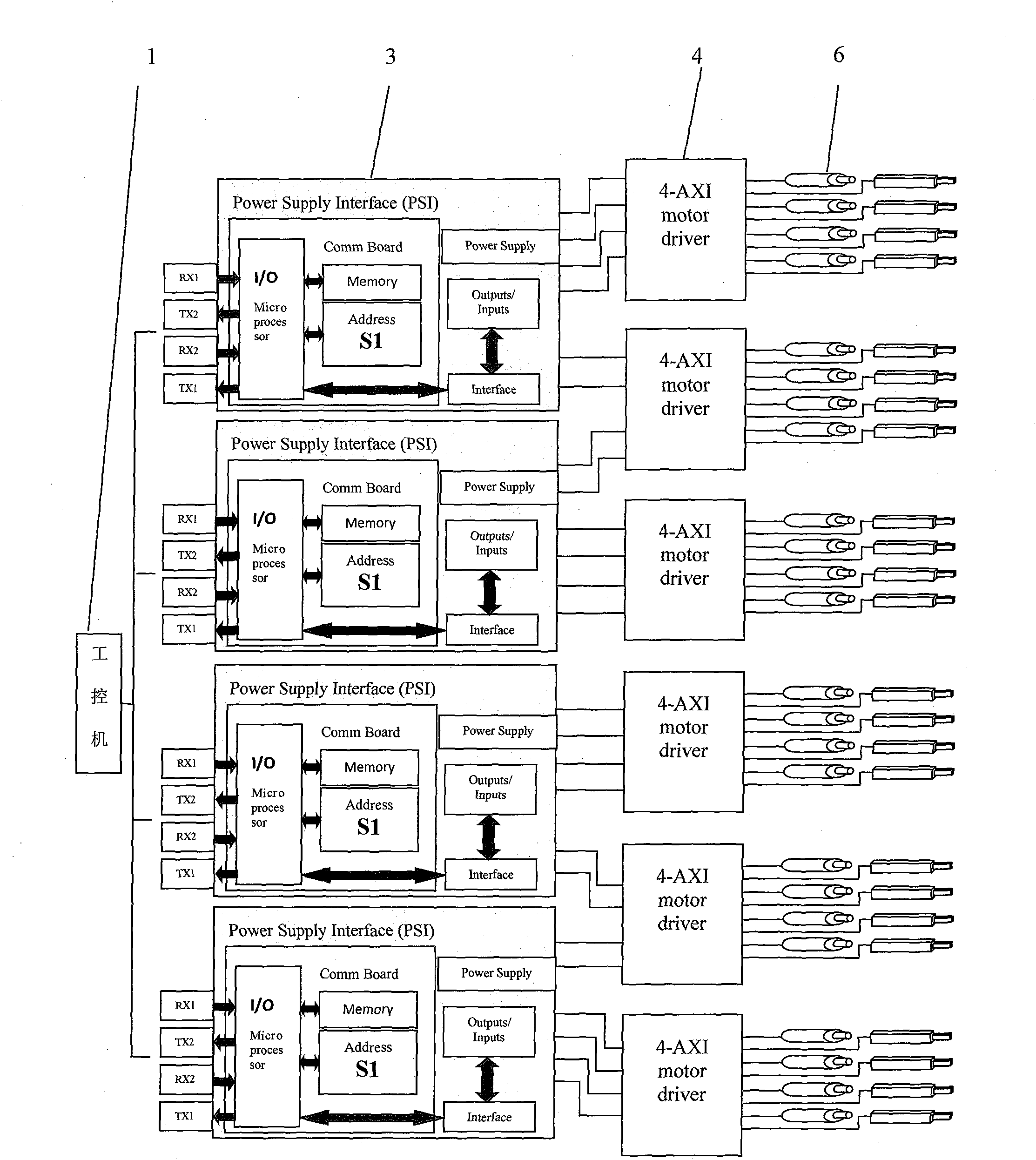
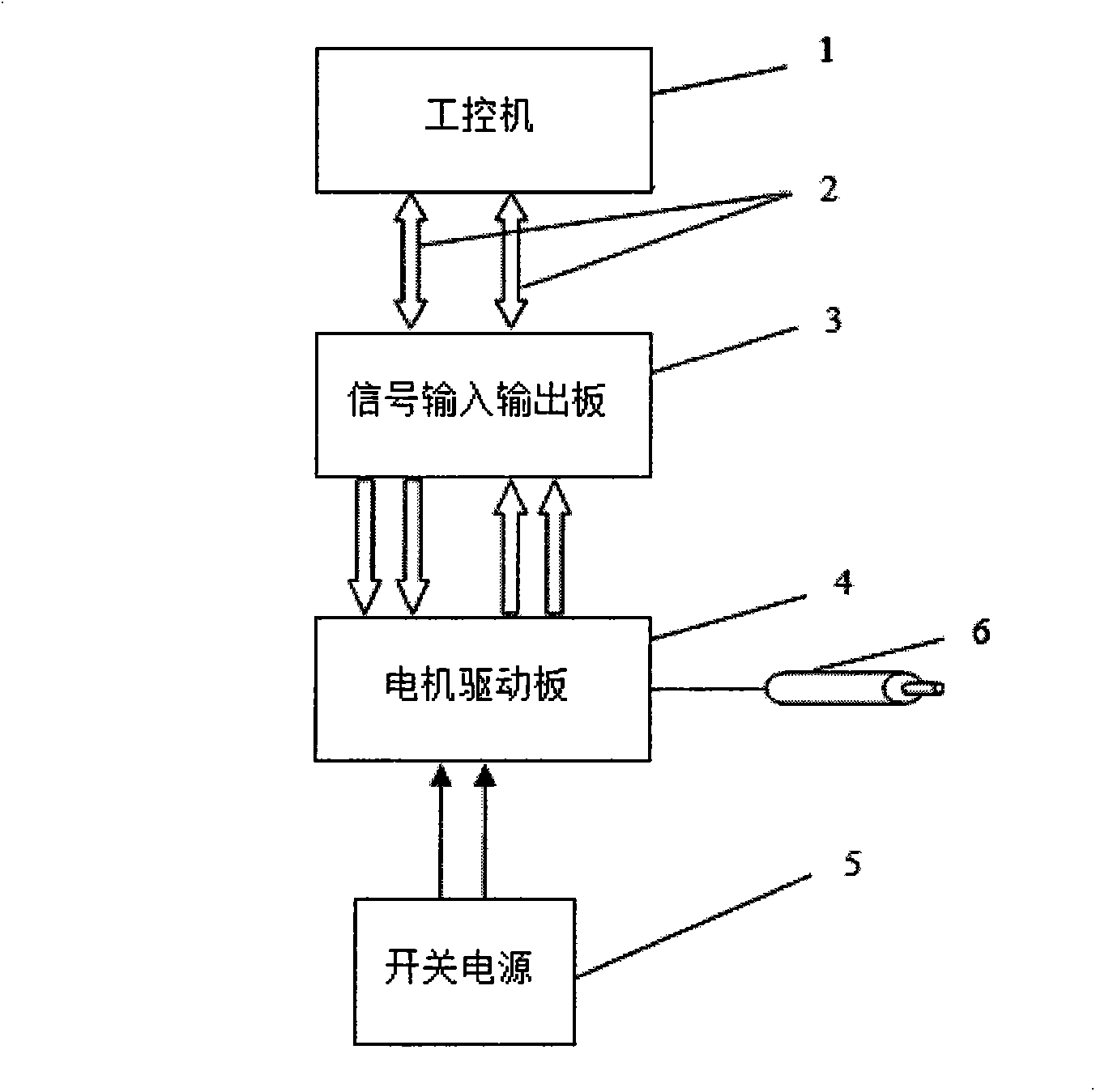
[0015] see figure 1 A control method for adjusting the movement of multi-magnetic poles, comprising an industrial computer (1), an optical fiber (2), a signal input and output board (3), a motor drive board (4), a switching power supply (5), and multi-magnetic poles (6).

[0016] The industrial computer (1) is connected to the signal input and output board (3) through an optical fiber (2) to send and receive data in real time, and the switching power supply (5) provides working voltage for the motor drive board (4), including the motor drive voltage and the displacement sensor. Voltage, the signal input and output board (3) is connected with the motor drive board (4), and the signal input and output board (3) sends the enable signal sent by the industrial computer (1) to the enable end of the m...


PUM


Abstract

The invention discloses a method for adjusting multi-magnetic-pole motion control. An industrial control computer (1), an optical fiber (2), a signal input and output board (3), a motor driving board (4), a switch power supply (5) and multiple magnetic poles (6) are included. The method for adjusting multi-magnetic-pole motion control is detailed in the instruction, and a specific embodiment scheme is further provided. The device relates to an ion injection device and belongs to the semi-conductor manufacturing field.

Description

technical field [0001] The invention relates to a technical field of adjusting the intensity of a local magnetic field by controlling the vertical movement of a magnetic pole by a motor, and is particularly applied in an ion implanter to change the deflection angle of a beam current passing through an adjustment area. Background technique [0002] With the continuous advancement of modern CMOS technology, the types of ion implantation processes are increasing, and with the reduction of characteristic line width and the increase of process complexity, the traditional medium beam implanter can no longer meet the requirements of this process. Therefore, The challenges faced by the ion implantation process are reflected in the development of the implantation energy to the ultra-low end, while the implantation dose is developed to the high concentration. To solve this manufacturing process, it is necessary to develop a new ion implanter equipment—a low-energy and large-beam ion im...

Claims


Application Information

Patent Timeline
Patent Type & Authority Applications(China)
IPC IPC(8): H01J37/15
CPCH01J37/15H01J37/3171H01J37/3266
Inventor 高婷婷
Owner BEIJING ZHONGKEXIN ELECTRONICS EQUIP
Learn More