
Automobile electric control hydraulic braking system and energy recycling method thereof

An electronically controlled hydraulic and braking system technology, applied in the direction of brakes, regenerative braking, braking components, etc., can solve the problems of low braking energy recovery utilization rate, limited application objects, high recovery efficiency, etc., and achieve obvious energy saving effects , simple structure, and the effect of reducing system cost

Inactive Publication Date: 2015-01-21
NANJING UNIV OF AERONAUTICS & ASTRONAUTICS
View PDF9 Cites 4 Cited by
  • Summary
  • Abstract
  • Description
  • Claims
  • Application Information

AI Technical Summary

Problems solved by technology

[0005] In order to overcome the shortcomings of the existing electronically controlled hydraulic braking system, such as complex structure, high cost, low braking energy recovery utilization rate, and limited application objects, the present invention provides an automotive electronically controlled hydraulic braking system and its energy recovery method , the system makes full use of the commonly used structural components in automobiles to realize the energy supply and energy recovery of the electronically controlled hydraulic braking system, which reduces the energy conversion link in the braking process, reduces energy loss, and has high recovery efficiency. It can be applied to motor drive and energy recovery at the same time Cars without electric motors

Method used


Image

  • Automobile electric control hydraulic braking system and energy recycling method thereof
  • Automobile electric control hydraulic braking system and energy recycling method thereof

Examples


Embodiment Construction

[0027] Below in conjunction with accompanying drawing, technical scheme of the present invention is described in further detail:

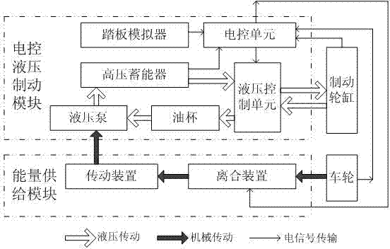
[0028] like figure 1 As shown, the present invention discloses an automotive electronically controlled hydraulic braking system, which includes an electronically controlled hydraulic braking module and an energy supply module.

[0029] Among them, the electronically controlled hydraulic brake module includes a pedal simulator, an electronic control unit, a high-pressure accumulator, a hydraulic pump, an oil cup, and a hydraulic control unit, and the energy supply module includes a transmission device and a clutch device.

[0030] The hydraulic pump is respectively connected to the high-pressure accumulator and the oil cup through the oil pipe; the oil inlet of the hydraulic control unit is connected to the high-pressure accumulator, the oil outlet is connected to the oil cup, and the control oil port is connected to the brake wheel cylinder.

[00...


PUM


Abstract

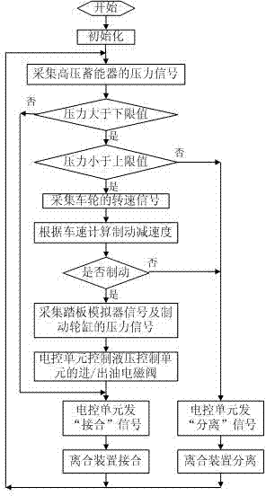
The invention discloses an automobile electric control hydraulic braking system and an energy recycling method thereof. The automobile electric control hydraulic braking system comprises an electric control hydraulic braking module and an energy supplying module. The electric control hydraulic braking module comprises a pedal simulator, an electric control unit, a high-pressure energy accumulator, a hydraulic pump, an oil cup and a hydraulic control unit. The energy supplying module comprises a transmission device and a clutch device. The electric control unit controls the states of oil inlet / outlet electromagnetic valves of the hydraulic control unit according to induction signals of the pedal simulator and pressure signals of a braking wheel cylinder and controls the state of the clutch device according to rotating speed signals of wheels and pressure signals of the high-pressure energy accumulator. When the clutch device is combined, the wheels are mechanically connected with the transmission device to drive the hydraulic pump to work, hydraulic oil in the oil cup is stored in the high-pressure energy accumulator. When the clutch device is separated, mechanical connection between the wheels and the transmission device is disconnected. Intelligent automobile braking and braking energy recycling can be achieved.

Description

technical field [0001] The invention relates to the field of automobile active safety and advanced braking systems, in particular to an automobile electronically controlled hydraulic braking system and an energy recovery method thereof, which can be applied to motor-driven and non-motor-driven automobiles. Background technique [0002] The braking system is an important guarantee for the safety performance of automobiles. With the continuous improvement of people's safety awareness, the requirements for the braking performance of automobiles are also increasing. As an advanced braking system, the electronically controlled hydraulic braking system cancels the vacuum booster, has a simple and compact structure, can individually control the braking force of each wheel, and is easy to integrate functions such as ABS, TCS, EBD, and ESP. It has wide application prospects in automobiles, so the electro-hydraulic braking system is considered to be the main product of the next genera...

Claims


Application Information

Patent Timeline
IPC IPC(8): B60T1/10B60T13/66
CPCB60T1/10B60T13/66B60T2270/60
Inventor 金智林段博文张甲乐王睿李明晔潘威田力
Owner NANJING UNIV OF AERONAUTICS & ASTRONAUTICS
Learn More