
A gas turbine exhaust system

A technology for exhaust systems and gas turbines, which is applied in the direction of gas turbine devices, mechanical equipment, engine components, etc., can solve problems affecting people's production and life, the impact of power plant economic benefits, and reduce the efficiency of gas turbines, so as to shorten the development cycle, light weight, Good high strength effect

Active Publication Date: 2015-12-02
江苏华强新能源科技有限公司
View PDF5 Cites 0 Cited by
  • Summary
  • Abstract
  • Description
  • Claims
  • Application Information

AI Technical Summary

Problems solved by technology

If the structural design of the exhaust system is unreasonable, resonance occurs or fails due to insufficient strength, it will cause a large displacement of the exhaust system, and the gas turbine cannot be discharged smoothly, which will affect the normal operation of the gas turbine, thereby reducing the efficiency of the gas turbine and even causing the shutdown of the gas turbine
Similarly, if the thermal design is unreasonable, it will cause overheating of the exhaust system casing and even gas leakage, which will endanger personal safety and cause the shutdown of the gas turbine
Due to the particularity of the power industry, the unplanned downtime of gas turbines will not only affect the economic benefits of the power plant itself, but also have an impact on the power grid. Timely downtime is likely to cause regional power outages, which will affect people's production and life

Method used


Image

  • A gas turbine exhaust system

Examples


Embodiment 1

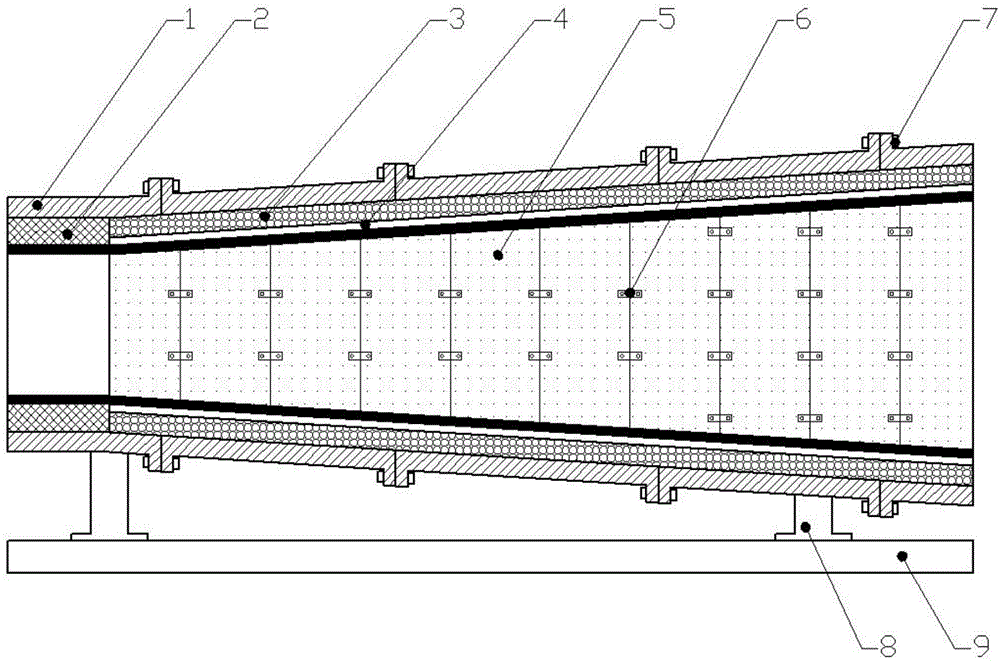
[0017] This embodiment provides a gas turbine exhaust system with a structure such as figure 1 As shown, it includes a shell 1, a seal 2, a gasket 5, a pressure plate 6, a connecting piece 7, a support 8 and a base 9. The shell 1 is a cylindrical steel plate structure with one end large and the other end small, and is connected by The parts 7 are assembled and connected. The gasket 5 is connected and fixed by bolts and nuts through the pressure plate 6. The seal 2 is arranged at the inner edge of the entrance of the small end of the shell 1. The upper end of the support 8 is connected to the bottom of the horizontal shell 1, and the support 8 The lower end is connected to the base 9, and also includes a heat dissipation layer 3 and an isolation layer 4. The heat dissipation layer 3 is arranged close to the inner wall of the housing 1. The isolation layer 4 is connected to the heat dissipation layer 3 and laid along the side wall. The other side of the isolation layer 4 is provi...


PUM


Abstract

The invention discloses an exhaust system of a gas turbine. The exhaust system comprises a shell, a sealing member, connecting pieces, a support, a pedestal, a heat dissipation layer, an isolating layer, a pad and a pressing plate, wherein the shell is of a transverse cylindrical steel plate structure with a big end and a small end and is assembled and connected by the connecting pieces; the sealing member is arranged on the inner edge of an inlet in the small end of the shell; the upper end of the support is connected below the transverse shell, and the lower end of the support is connected with the pedestal; the heat dissipation layer is tightly attached to the inner wall of the shell; the isolating layer is connected with the heat dissipation layer and is laid along the side wall; the pad is arranged on the other side of the isolating layer and is fixedly connected through the pressing plate by using bolts and nuts. According to the product, the heat efficiency can be integrally improved, the thermal stress produced by non-uniform heating on a heated surface is relieved, stress concentration is avoided, and the safety of operation is improved; meanwhile, the failure condition in operation of the conventional products can also be eliminated, and the product cost is reduced and the development period is shortened on the premise of guaranteeing the product quality.

Description

technical field [0001] The invention belongs to the technical field of gas turbines, and relates to a gas turbine exhaust system. Background technique [0002] Due to the rapid development of my country's economy, the demand for electric energy continues to grow, but with the increasingly serious problem of global warming and the increasingly scarce mineral resources, the demand for various clean energy is particularly important. [0003] Gas turbine combined cycle (GTCC), also known as gas-steam combined cycle, refers to a power generation method that combines gas turbines and steam turbines, mainly consisting of gas turbines (compressors, combustion chambers, turbines, control systems and auxiliary systems), It consists of three parts: waste heat boiler and steam turbine. The compressor inhales and compresses the air and sends it into the combustion chamber, so that the fuel (oil or natural gas) is burned to produce high-temperature and high-pressure gas, which enters the...

Claims


Application Information

Patent Timeline
Patent Type & Authority Patents(China)
IPC IPC(8): F01D25/30F02C7/28
Inventor 邬文泰陈欣
Owner 江苏华强新能源科技有限公司
Learn More