
Electromagnetic principle-based driving belt with automatic sieving function

A technology based on automatic screening and electromagnetic principles, which is applied in the direction of conveyor objects, transportation and packaging, etc., can solve the problems of difficult to be efficiently applied in the industrial field, unable to operate synchronously, and the selection of items is single.

Active Publication Date: 2015-01-07
HUNAN CHANGZHONG MACHINERY
View PDF7 Cites 4 Cited by
  • Summary
  • Abstract
  • Description
  • Claims
  • Application Information

AI Technical Summary

Problems solved by technology

In the field of garbage sorting, although CN201310251001.9 and CN201320361496.6 disclose a magnetic separator for recycling metal garbage, the transmission and screening are not integrated structures and cannot run synchronously, and the types of items to be selected are single, which is difficult to obtain in the industrial field. efficient application

Method used


Image

  • Electromagnetic principle-based driving belt with automatic sieving function
  • Electromagnetic principle-based driving belt with automatic sieving function
  • Electromagnetic principle-based driving belt with automatic sieving function

Examples


specific Embodiment 1

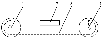
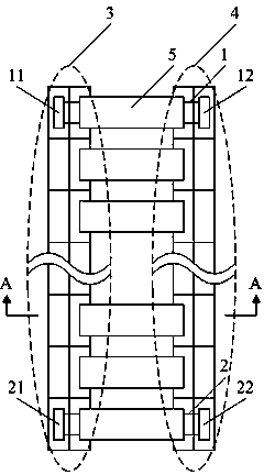
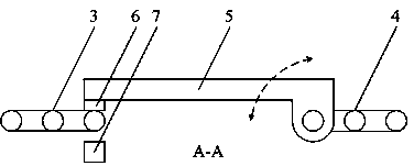
[0019] A conveyor belt with automatic screening function based on electromagnetic principles in this embodiment, the front view is as follows figure 1 shown; top view as figure 2 As shown, the direction from left to right in the top view is the direction from front to back described in the embodiment; image 3 yes figure 2 A schematic diagram of the A-A direction. The conveyor belt includes a drive shaft (1), a driven shaft (2) and a conveyor belt; the drive shaft (1) is provided with a drive front gear (11) and a drive rear gear (12), and the drive shaft (2) A driven front gear (21) and a driven rear gear (22) are provided; the driving front gear (11) and the driven front gear (21) are in the same vertical plane, driving the front chain (3) to form a circle Angular rectangular shape rotation, the driving rear gear (12) and the driven rear gear (22) are in the same vertical plane, driving the rear chain (4) to rotate in a rounded rectangular shape; the front chain (3) inc...

specific Embodiment 2

[0022] In this embodiment, on the basis of the specific embodiment 1, a controller (9) is added, and the control output end of the controller (9) is connected to the repelling electromagnet (7) and the attracting electromagnet (8), and the connection method is Parallel connection, at the same time, the driving shaft (1) is driven by the motor to rotate, and the speed data of the motor is sent to the controller (9) through the data input terminal of the controller (9). The schematic diagram of the circuit structure is as follows Figure 4 shown.

[0023] If the item to be tested on the conveyor belt is detected to be unqualified, the controller (9) calculates the speed of the conveyor belt according to the rotation speed of the motor, and calculates the The action time of the repelling electromagnet (7) is obtained, and when the item to be tested is conveyed above the repelling electromagnet (7) by the conveyor belt, the controller (9) sends a signal to the repelling electromag...


PUM


Abstract

The invention discloses an electromagnetic principle-based driving belt with an automatic sieving function and belongs to the field of material sorting and conveying. The driving belt is provided with a sieving plate, the front end of the sieving plate is lapped on the third sub-chain of a front chain from the front to the back, the rear end is in shaft connection with the first sub-chain of a rear chain from the front to the back and rotates around the first sub-chain of the rear chain from the front to the back, a permanent magnet is arranged at the bottom of the front end of the sieving plate, a repellent electromagnet and an attractive electromagnet are longitudinally arranged in the plane with a drive front gear and a driven front gear, and the polarities of the attractive electromagnet and repellent electromagnet are opposite. By means of the structure, the electromagnetic principle-based driving belt with the automatic sieving function realizes the integration and synchronous running of conveying and sieving, optimizes the material sieving streamline and is capable of directly sieving objects according to the object quality without additional equipment.

Description

technical field [0001] A conveyor belt with an automatic screening function based on an electromagnetic principle belongs to the field of material selection and transmission. Background technique [0002] In the middle of the 17th century, the United States began to use aerial ropeways to convey bulk materials; in the middle of the 19th century, conveyor belt conveyors of various modern structures appeared one after another. In 1868, belt conveyors appeared in the UK; in 1887, screw conveyors appeared in the United States; in 1905, steel belt conveyors appeared in Switzerland; in 1906, inertial conveyors appeared in the UK and Germany. Since then, the conveyor belt conveyor has been continuously improved under the influence of technological progress in machinery manufacturing, electrical machinery, chemical industry and metallurgical industry. An integral part of the mechanization and automation of material handling systems. [0003] As the industry continues to grow, the ...

Claims


Application Information

Patent Timeline
Patent Type & Authority Applications(China)
IPC IPC(8): B65G47/34
Inventor 万正喜肖熳
Owner HUNAN CHANGZHONG MACHINERY
Learn More