Method for retreading of loader tyre
A loader and tire technology, applied in the field of grinding tooling, can solve the problems of weakening the protective effect of the tire tread on the carcass, puncturing and blasting of the tire ply, and reducing the impact resistance performance of the elastic domain, so as to reduce the tread Concave and convex phenomenon, convenient and timely adjustment, the effect of preventing deformation
- Summary
- Abstract
- Description
- Claims
- Application Information
AI Technical Summary
Problems solved by technology
Method used
Image
Examples
Embodiment 1
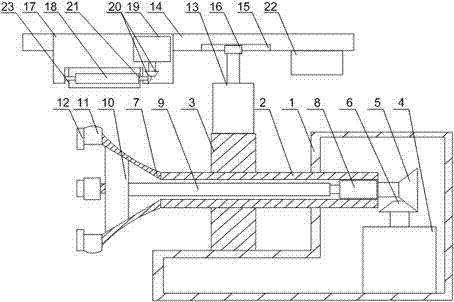
[0023] Such as Figure 1 to Figure 2As shown, the tire retreading method of the present invention is to place the tire to be retreaded on the expansion clamping part, start the first cylinder 8, the output end of the first cylinder 8 retracts, and drives the connecting rod 9 to the DC motor 4 One side moves, at this time the slider 10 is in contact with the expansion clamping part, and the volume of the expansion clamping part increases under the action of the front top of the slider 10, and the outer wall of the expansion clamping part contacts the middle part of the tire, thereby realizing Clamping of the tire; when the tire is clamped stably, turn the DC motor 4, and the pinion 6 on the output end of the DC motor 4 cooperates with the large gear 5 at the end of the sleeve 2, so that the expansion clamping part drives the tire in the L-shaped Rotate and move on support base 1, facilitate retreading cutter 18 to process tire, when processing is finished, DC motor 4 stops rota...
Embodiment 2
[0026] Such as Figure 1 to Figure 2 As shown, this embodiment is based on Embodiment 1, the expansion clamping part includes an elastic expansion cover 7, the small diameter end of the elastic expansion cover 7 is connected to the sleeve 2, and the elastic expansion cover 7 A claw 11 is installed on the large diameter end, and the upper end surface of the claw 11 is arc-shaped. When clamping the tire, the elastic expansion cover 7 passes through the inner side of the bead, and the claws 11 are in contact with the inner wall of the bead. stability, and when the sleeve 2 rotates, it avoids slipping between the inner wall of the bead and the claw 11, and further reduces the unevenness when cutting the tread.
Embodiment 3
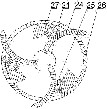
[0028] Such as figure 2 As shown, on the basis of Embodiment 1, the present embodiment includes a cylindrical body 26 and a rotating shaft 21, the rotating shaft 21 is arranged in the cylindrical body 26, the two ends of the rotating shaft 21 protrude from the two ends of the cylindrical body 26, and the rotating shaft 21 One end is rotatably connected to the tool holder 17, the other end of the rotating shaft 21 is connected to the bevel gear 20, and a plurality of arc-shaped blades 24 are uniformly arranged on the rotating shaft 21, and the arc-shaped blades 24 are hinged to the rotating shaft 21. 26 is provided with an opening corresponding to the arc-shaped blade 24, and the arc-shaped blade 24 runs through the opening. A block 27 is arranged on the inner wall of the cylinder 26. One side of the block 27 is an arc-shaped concave surface, and the arc-shaped concave surface and the arc-shaped The arc outer sides of the blades 24 are connected by a spring 25 . Rotating shaf...
PUM
 Abstract
Description
Claims
Application Information
 - R&D Engineer
- R&D Manager
- IP Professional
- Industry Leading Data Capabilities
- Powerful AI technology
- Patent DNA Extraction
Browse by: Latest US Patents, China's latest patents, Technical Efficacy Thesaurus, Application Domain, Technology Topic, Popular Technical Reports.
© 2024 PatSnap. All rights reserved.Legal|Privacy policy|Modern Slavery Act Transparency Statement|Sitemap|About US| Contact US: help@patsnap.com


