Cleaning sieve

A vibrating screen and hopper technology, which is applied in the field of cleaning screens, can solve the problems of not being easy to fix the dust collection bag, affecting the dust collection efficiency, and increasing the dust at the feeding place, so as to facilitate transportation and storage area movement, solve dust escape, The effect of increasing throughput

Active Publication Date: 2014-12-31
HUBEI YEWEI OILS GRP MACHINERY
View PDF6 Cites 7 Cited by
  • Summary
  • Abstract
  • Description
  • Claims
  • Application Information

AI Technical Summary

Problems solved by technology

The technical difficulties of the existing cleaning sieve mainly include: low efficiency of the winnowing and dust removal system; high air pressure at the slag outlet of the winnowing and dust removing system, causing dust, and as the processing capacity increases, the dust at the feed of the cleaning sieve It also increases and deteriorates the working site environment; it is not easy to fix the dust collection bag at the slag outlet of the winnowing dust removal system, which affects the dust collection efficiency and cannot meet the requirements of large processing capacity of the equipment; the discharge port of the equipment is located at the bottom, which is not conducive to The cleaned materials are collected; the feeding speed of the feeding system is slow and uneven; the entire cleaning screen cannot move by itself, and the flexibility of use is limited; the axis of the dust collector of the wind separation dust removal system is set along the vertical direction, and the dust removal The lower end of the dust collector is connected to the dust conveying device of the winnowing dust removal system through the dust conveying pipe. The height of the dust collector is relatively high and the dust conveying pipe is easy to be blocked.

Method used


Image

  • Cleaning sieve
  • Cleaning sieve

Examples


Embodiment Construction

[0040] Specific embodiments of the present invention will be described in detail below in conjunction with the accompanying drawings. It should be understood that the specific embodiments described here are only used to illustrate and explain the present invention, and are not intended to limit the present invention.

[0041] In the present invention, in the case of not stating otherwise, the orientation words used such as "upper, lower" and "vertical, horizontal" are usually defined in the normal use of the cleaning screen provided by the present invention, and are also related to Reference attached figure 1 The directions shown in are the same; "inner and outer" refer to the inner and outer relative to the outline of each part itself.

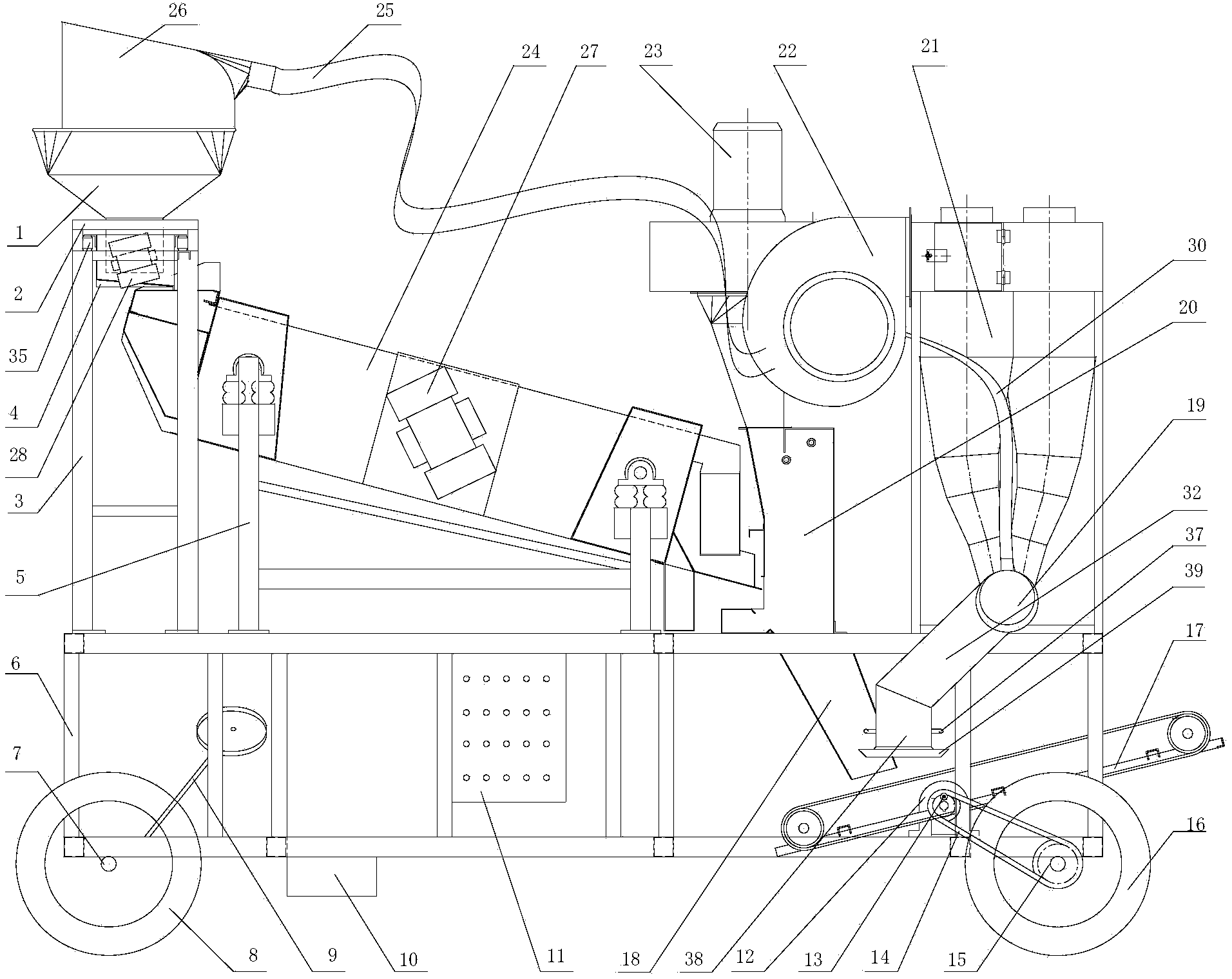
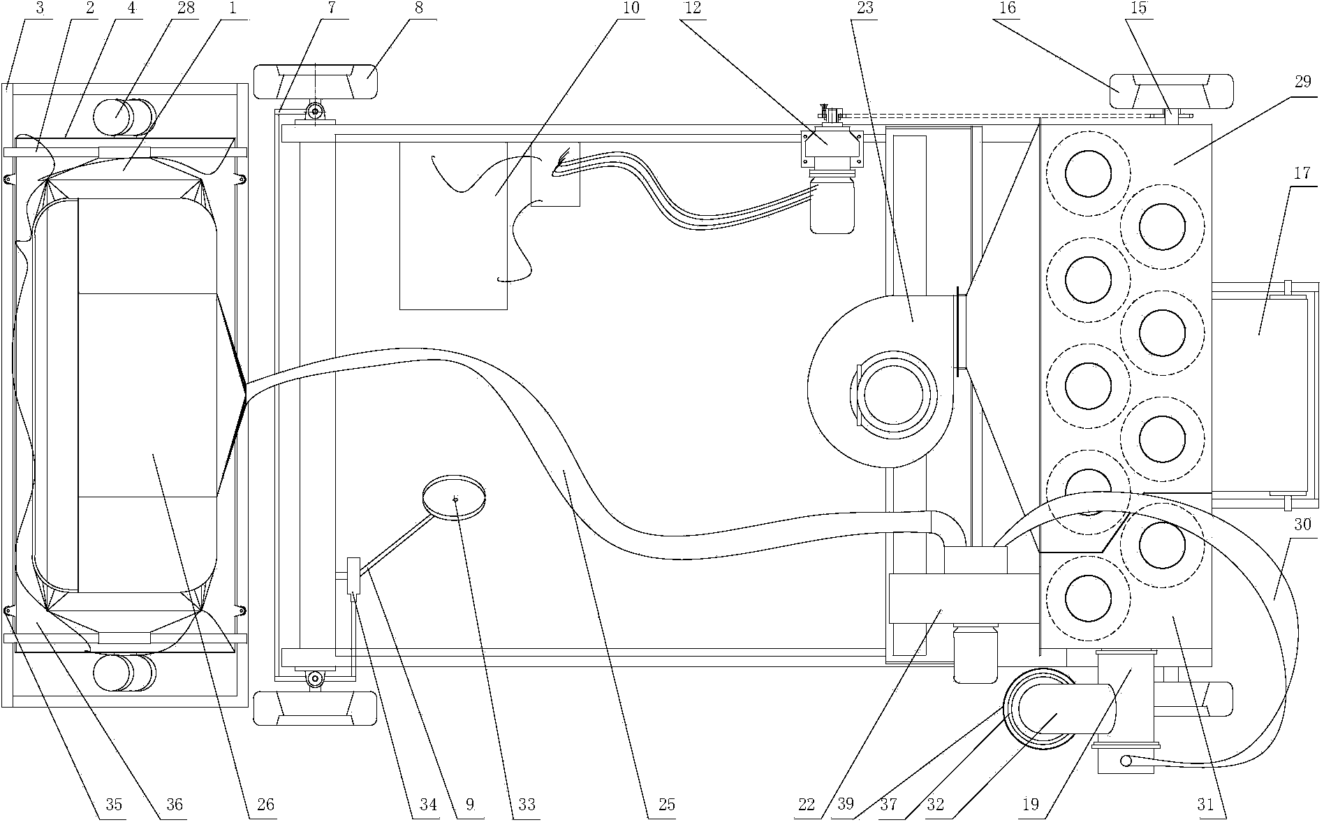
[0042] The invention provides a cleaning sieve, which can be used for sorting materials, especially for cleaning grains and the like.

[0043] The cleaning screen of the present invention includes a frame and a feeding system installed on t...


PUM


Abstract

The invention discloses a cleaning sieve. The cleaning sieve comprises a machine frame, a feeding system, a vibrating screen and a wind-selection dust-removing system, wherein the feeding system, the vibrating screen and the wind-selection dust-removing system are arranged on the machine frame and are sequentially connected; the wind-selection dust-removing system comprises a wind-selection device, a primary dust-removing unit, a secondary dust-removing unit, a dust collecting device and a pressure-reduction dust-sucking pipe; the wind-selection device is provided with an inlet and a dust outlet; the inlet of the wind-selection device is connected to a discharging outlet of the vibrating screen; the dust outlet is connected to an air inlet of the primary dust-removing unit; the dust collecting device comprises a dreg inlet and a dreg outlet; a dust-discharging opening of the primary dust-removing unit and a dust-discharging opening of the secondary dust-removing unit are connected to the dreg inlet of the dust collecting device; one end of the pressure-reduction dust-sucking pipe is connected to an air inlet of the secondary dust-removing unit; the other end of the pressure-reduction dust-sucking pipe is connected to the place close to the dreg outlet of the dust collecting device.

Description

technical field [0001] The invention relates to the field of grain processing, in particular to a cleaning sieve. Background technique [0002] The current grain cleaning equipment on the market cannot simultaneously meet the needs of large processing capacity, efficient and environmentally friendly cleaning, efficient dust removal and efficient recycling. The existing cleaning screen generally includes a frame and a feeding system installed on the frame and connected in sequence, a vibrating screen and a wind separation dust removal system. The material enters the vibrating screen through the feeding system, and after being sorted by the vibrating screen, the large particles The impurities are directly discharged from the slag discharge port of the vibrating screen, and the materials and impurities with particle size meeting the requirements are discharged from the discharge port of the vibrating screen to the air separation and dust removal system. The discharge port of t...

Claims


Application Information

Patent Timeline
Patent Type & Authority Applications(China)
IPC IPC(8): B07B9/02B07B11/06B07B11/08B07B11/00B07B11/02
Inventor 叶维林蔡军
Owner HUBEI YEWEI OILS GRP MACHINERY
Why Eureka
Try Eureka